Hello readers, welcome to our informative article on the 12v ignition coil ballast resistor wiring diagram. In this article, we will provide you with a detailed explanation of the wiring diagram, its advantages, disadvantages, and alternative options. So, let’s dive right into it!
1. Understanding the 12v Ignition Coil Ballast Resistor Wiring Diagram
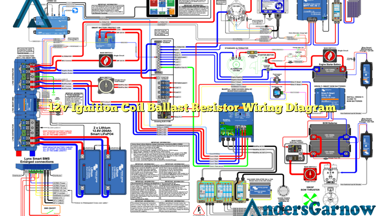
The 12v ignition coil ballast resistor wiring diagram is a schematic representation of the electrical connections required for the proper functioning of the ignition coil in a 12-volt system. This diagram illustrates how the ballast resistor is wired in series with the ignition coil to regulate the voltage and prevent the coil from overheating.
In simple terms, the ballast resistor acts as a voltage stabilizer, ensuring that the ignition coil receives a constant voltage supply. This is crucial because excessive voltage can damage the ignition coil, while insufficient voltage can result in weak or no spark, leading to engine misfires.
2. Advantages of Using a Ballast Resistor
The inclusion of a ballast resistor in the ignition coil circuit offers several advantages:
- Protection: The ballast resistor protects the ignition coil from overheating by limiting the voltage that reaches it. This extends the lifespan of the coil and prevents premature failures.
- Stable Voltage: By reducing the voltage supplied to the ignition coil, the ballast resistor ensures a stable and consistent voltage, resulting in reliable engine performance.
- Compatibility: The ballast resistor allows for the use of a 12-volt ignition coil in a 6-volt electrical system without the need for additional modifications.
3. Disadvantages of Using a Ballast Resistor
While the ballast resistor offers numerous benefits, it is essential to consider its drawbacks as well:
- Reduced Spark Energy: The ballast resistor reduces the voltage supplied to the ignition coil, which, in turn, decreases the spark energy. This can result in slightly weaker spark plugs and potentially impact engine performance.
- Compatibility Limitations: The ballast resistor is primarily designed for use in 12-volt systems. It may not be suitable for other voltage configurations, requiring alternative solutions.
4. Alternative Options
If you prefer not to use a ballast resistor, there are alternative options available:
- Electronic Ignition Systems: Electronic ignition systems, such as the HEI (High Energy Ignition), eliminate the need for a ballast resistor. These systems provide a constant voltage to the ignition coil, resulting in improved performance and reliability.
- Resistor Wire: Some vehicles use a resistor wire instead of a ballast resistor. This wire is built with resistance, which reduces the voltage supplied to the ignition coil. However, it is crucial to ensure the correct resistance value for compatibility.
5. 12v Ignition Coil Ballast Resistor Wiring Diagram
| Wire Color | Description |
|---|---|
| Red | Power supply from the ignition switch |
| Black | Ground connection |
| Orange | Output connection to the ignition coil |
| Green | Connection to the ballast resistor |
| Purple | Connection to the starter solenoid |
Frequently Asked Questions (FAQ)
Q: Can I bypass the ballast resistor?
A: Yes, it is possible to bypass the ballast resistor in certain cases. However, it is crucial to understand the implications and ensure compatibility with your ignition system.
Q: How can I test if my ballast resistor is functioning correctly?
A: To test the ballast resistor, you can use a multimeter to measure the voltage across its terminals. A healthy ballast resistor should display the expected resistance and provide a stable voltage output.
Q: Is a ballast resistor necessary for all ignition systems?
A: No, not all ignition systems require a ballast resistor. Modern electronic ignition systems often eliminate the need for a ballast resistor by providing a constant voltage supply to the ignition coil.
Thank you for reading our comprehensive article on the 12v ignition coil ballast resistor wiring diagram. We hope that this information has provided you with valuable insights into this essential component of the ignition system.

