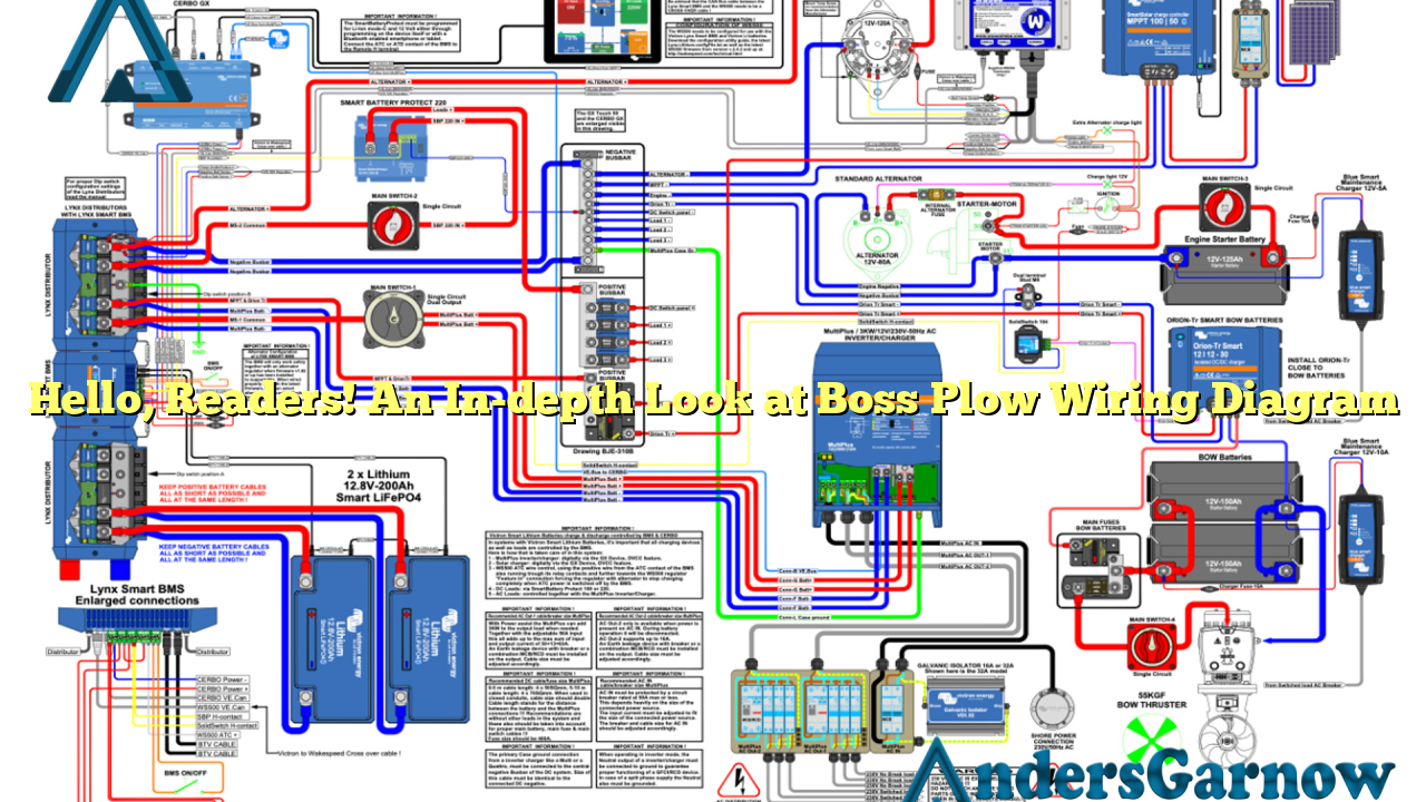
Welcome to our comprehensive guide on Boss Plow Wiring Diagram. In this article, we will delve into the intricacies of Boss plow wiring and provide you with all the information you need to know. Whether you are a professional snowplow operator or a do-it-yourself enthusiast, understanding the wiring diagram is essential for the smooth functioning of your Boss plow. So, let’s get started!
1. Understanding the Basics of Boss Plow Wiring Diagram
Before we dive into the specifics, let’s have a brief overview of what a Boss Plow Wiring Diagram is. It is a visual representation of the electrical connections and components of your Boss plow. The diagram illustrates how power flows through the system, allowing you to identify and troubleshoot any issues that may arise.
The diagram consists of various symbols and lines that represent different parts of the wiring system. By following the diagram, you can easily identify the connections between the battery, controller, solenoid, and other components. This understanding is crucial for maintaining and repairing your Boss plow effectively.
2. The Advantages of Using Boss Plow Wiring Diagram
One of the significant advantages of having a Boss Plow Wiring Diagram is its ability to simplify complex wiring systems. It provides a clear and concise visual representation, making it easier for technicians to identify and rectify any issues. This saves time and effort during troubleshooting, ultimately reducing downtime.
Additionally, the diagram ensures proper installation of the plow wiring system. It eliminates guesswork and minimizes the risk of incorrect connections, which can result in damage to the plow or even pose safety hazards. Following the wiring diagram ensures a safe and efficient operation of your Boss plow.
3. Exploring the Components of Boss Plow Wiring Diagram
The Boss Plow Wiring Diagram consists of several key components that are essential for its proper functioning. These components include:
| Component | Description |
|---|---|
| Battery | Provides the power source for the plow system |
| Controller | Allows the operator to control the plow’s movement and functions |
| Solenoid | Acts as a switch to control the flow of power to the plow’s motor |
| Motor | Drives the plow’s hydraulic system |
| Lights | Illuminate the plow and provide visibility during operation |
Understanding the role of each component and their interconnections is crucial for troubleshooting and maintaining the system.
4. Step-by-Step Guide to Reading Boss Plow Wiring Diagram
Reading a Boss Plow Wiring Diagram may seem daunting at first, but with a systematic approach, it becomes much easier. Here is a step-by-step guide to help you navigate through the diagram:
- Identify the key components and their symbols on the diagram.
- Follow the lines to trace the flow of power from the battery to the various components.
- Pay attention to the connections and ensure they are correctly represented.
- Refer to the legend or key for any unfamiliar symbols or abbreviations.
- Use a multimeter or continuity tester to verify the continuity of wires and connections.
By following these steps, you will be able to interpret and utilize the Boss Plow Wiring Diagram effectively.
5. Common Issues and Troubleshooting Tips
Despite its reliability, the Boss plow wiring system may encounter issues occasionally. Here are some common problems and troubleshooting tips:
- Issue: Plow does not respond to controller commands. Check the connections between the controller, solenoid, and motor. Ensure they are secure and free from corrosion. Test the controller for proper functioning.
- Issue: Lights do not work. Inspect the wiring connections for loose or damaged wires. Check the bulbs and replace them if necessary. Test the light switch and wiring harness for any faults.
- Issue: Plow operates intermittently. Examine the wiring connections for loose or frayed wires. Check the solenoid and motor for any malfunctions. Test the battery voltage and ensure it is within the recommended range.
Remember to consult the Boss Plow Wiring Diagram to identify and rectify any issues effectively.
6. Alternative Wiring Diagrams for Boss Plows
Besides the standard Boss Plow Wiring Diagram, there are a few alternative options available. These alternative diagrams cater to specific models or customized installations. It is essential to refer to the appropriate diagram for your specific requirements. You can find these alternative diagrams on the official Boss website or by consulting a certified technician.
Conclusion
In conclusion, understanding the Boss Plow Wiring Diagram is vital for the smooth operation and maintenance of your plow. It simplifies complex wiring systems, ensures proper installation, and aids in troubleshooting. By referring to the diagram, you can identify and rectify any issues efficiently, minimizing downtime and optimizing productivity. Remember to follow safety precautions and consult a professional if you encounter any difficulties. Happy plowing!

