Hello readers! Today, we will be discussing the topic of air handler wiring diagram in detail. An air handler is an essential component of a heating, ventilation, and air conditioning (HVAC) system. It is responsible for circulating conditioned air throughout a building. Understanding the wiring diagram is crucial for proper installation, maintenance, and troubleshooting. So, let’s dive into the world of air handler wiring diagrams!
1. What is an Air Handler Wiring Diagram?
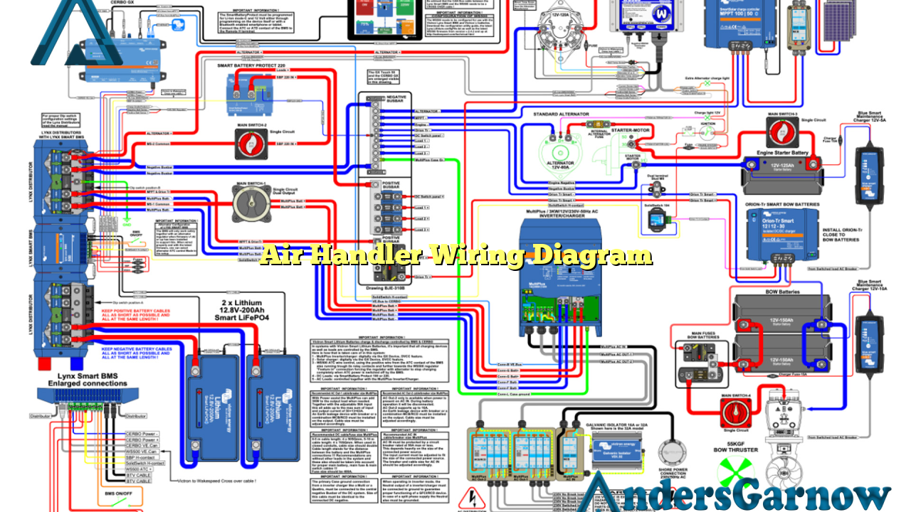
An air handler wiring diagram is a schematic representation of the electrical connections and components within an air handler unit. It provides a visual guide for technicians to understand and work on the electrical system of the air handler. The diagram typically includes information about the power supply, control circuits, fan motor, heat strips, and other relevant components.
2. Components of an Air Handler Wiring Diagram
The main components that are usually included in an air handler wiring diagram are:
| Component | Description |
|---|---|
| Power Supply | Shows the electrical connections for the incoming power supply to the air handler unit. |
| Control Circuits | Illustrates the wiring connections for various control components, such as thermostats, relays, and sequencers. |
| Fan Motor | Displays the wiring connections for the fan motor, including the speed settings and capacitor connections. |
| Heat Strips | Shows the wiring connections for the heating elements, which are used for supplemental heat in the air handler. |
| Other Components | May include wiring information for additional components like humidifiers, air filters, and UV lights. |
Understanding these components and their connections is essential for proper installation and troubleshooting purposes.
3. Advantages of Air Handler Wiring Diagrams
There are several advantages to having a detailed air handler wiring diagram:
- Easy Installation: The wiring diagram provides a clear understanding of how the electrical connections should be made during installation, ensuring a smooth and error-free process.
- Accurate Troubleshooting: When issues arise, the wiring diagram can be used as a reference to identify and resolve any electrical problems within the air handler unit.
- Efficient Maintenance: Technicians can refer to the wiring diagram for routine maintenance tasks, such as replacing components or inspecting wiring connections.
- Enhanced Safety: By following the wiring diagram, technicians can ensure that all electrical connections are made correctly, minimizing the risk of electrical hazards.
4. Disadvantages of Air Handler Wiring Diagrams
While air handler wiring diagrams offer numerous benefits, there are a few potential drawbacks:
- Complexity: Wiring diagrams can be complex and overwhelming, especially for individuals without a strong electrical background. It may require additional training or experience to interpret the diagram accurately.
- Limited Information: Wiring diagrams may not provide detailed information about specific components, such as their specifications or maintenance requirements. Additional resources may be required for comprehensive knowledge.
- Model Variations: Different air handler models may have variations in their wiring diagrams. Technicians must ensure they have the correct diagram for the specific unit they are working on.
5. Alternative Air Handler Wiring Diagrams
While traditional air handler wiring diagrams are widely used, there are alternative options available as well. One such alternative is the use of digital or interactive wiring diagrams. These diagrams offer a more user-friendly experience by allowing technicians to interact with the diagram, zoom in on specific sections, or access additional information with just a few clicks.
Digital wiring diagrams can also include features like color-coding, highlighting, and interactive troubleshooting guides, making them a valuable tool for technicians in the HVAC industry.
Conclusion
In conclusion, understanding the air handler wiring diagram is crucial for HVAC technicians. It provides a visual representation of the electrical connections and components within the air handler unit. While it offers several advantages, such as easy installation, accurate troubleshooting, efficient maintenance, and enhanced safety, there are also potential disadvantages, including complexity, limited information, and model variations. Exploring alternative options like digital wiring diagrams can further enhance the technician’s experience. By utilizing these resources effectively, technicians can ensure the proper functioning of air handler units and provide quality service to their customers.
Frequently Asked Questions (FAQ)
Q: Can I install an air handler without referring to the wiring diagram?
A: It is highly recommended to refer to the air handler wiring diagram during installation to ensure the correct electrical connections are made. Incorrect wiring can lead to system malfunctions or even damage to the unit.
Q: How can I obtain the correct air handler wiring diagram for my unit?
A: The air handler’s manufacturer usually provides the wiring diagram in the unit’s installation manual. If you don’t have access to the manual, you can contact the manufacturer’s customer support or visit their official website to obtain the necessary wiring diagram.
Q: Is it safe to work on the electrical components of an air handler?
A: Working on electrical components can be dangerous if proper safety precautions are not followed. It is recommended to turn off the power supply and consult a qualified HVAC technician for any electrical work on the air handler unit.
