Hello readers! In this article, we will delve into the world of alternator wiring diagrams. Alternators play a crucial role in a vehicle’s electrical system, providing power to the battery and various electrical components. Understanding the wiring diagrams associated with alternators is essential for ensuring proper installation and troubleshooting. So, let’s explore the intricacies of alternator wiring diagrams and gain a deeper insight into this vital automotive component.
1. The Basics of Alternator Wiring Diagrams
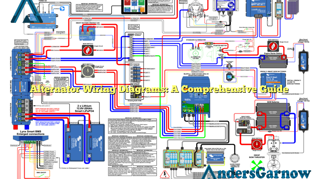
Alternator wiring diagrams illustrate the electrical connections between the alternator, battery, and other components. These diagrams provide a visual representation of the wiring setup and aid in understanding the various connections required for the alternator to function correctly. By referring to these diagrams, technicians can identify the appropriate wires and terminals, ensuring a proper and efficient electrical system.
One of the key aspects of alternator wiring diagrams is the identification of different wires and their corresponding functions. The main wires include the battery positive (+) wire, the battery negative (-) wire, the field wire, the stator wire, and the ignition switch wire. Understanding the purpose of each wire is crucial for accurate installation and troubleshooting.
Advantages of Alternator Wiring Diagrams
1. Clear Visual Representation: Alternator wiring diagrams provide a clear and concise visual representation of the electrical connections, making it easier to understand the setup.
2. Troubleshooting Aid: These diagrams act as a valuable tool for troubleshooting electrical issues related to the alternator or its associated components. Technicians can trace the wiring and identify potential problems quickly.
3. Standardization: Alternator wiring diagrams follow a standardized format, making it easier for technicians to interpret and work with them. This ensures consistency and accuracy across different vehicle models.
Disadvantages of Alternator Wiring Diagrams
1. Complexity: For individuals with limited electrical knowledge, alternator wiring diagrams can appear complex and overwhelming. The intricate connections and multiple wires may pose challenges in understanding the diagram.
2. Model Variations: While alternator wiring diagrams follow a standardized format, there may be variations between different vehicle models. It is essential to consult the specific wiring diagram for a particular vehicle to ensure accuracy.
2. Understanding Wire Colors and Symbols
Wire colors and symbols play a vital role in alternator wiring diagrams. They help identify different wires, their functions, and the appropriate connections. Here are some common wire colors and symbols found in alternator wiring diagrams:
| Wire Color | Symbol | Function |
|---|---|---|
| Red | + | Battery Positive |
| Black | – | Battery Negative/Ground |
| Yellow | F | Field Wire |
| White | S | Stator Wire |
| Pink | IGN | Ignition Switch Wire |
Understanding these wire colors and symbols is essential for accurate interpretation of alternator wiring diagrams. It enables technicians to identify the correct wires and establish the necessary connections, ensuring a properly functioning alternator system.
3. Common Alternator Wiring Diagram FAQs
Q: Can I use a generic alternator wiring diagram for any vehicle?
A: While some aspects of alternator wiring diagrams are standardized, it is recommended to refer to the specific wiring diagram for the vehicle model in question. Different vehicles may have variations in wiring connections and wire colors.
Q: How can I troubleshoot alternator wiring issues?
A: If you are experiencing electrical problems related to the alternator, consult the alternator wiring diagram specific to your vehicle model. Trace the wires, check for loose connections, damaged wires, or faulty components. Additionally, using a multimeter can help identify voltage irregularities.
Q: Are there any safety precautions to consider when working with alternator wiring?
A: When working with alternator wiring, always disconnect the battery before starting any repairs or modifications. This ensures safety and prevents the risk of electrical shock.
In Conclusion
In conclusion, alternator wiring diagrams are invaluable resources for understanding the electrical connections associated with alternators. They provide a clear visual representation of the wiring setup, aiding in installation and troubleshooting. While they may appear complex to those with limited electrical knowledge, understanding wire colors and symbols can simplify the interpretation process. By referring to the specific wiring diagram for a particular vehicle model, technicians can ensure accurate connections and a properly functioning alternator system. Remember to prioritize safety by disconnecting the battery before any electrical work. We hope this comprehensive guide has shed light on the world of alternator wiring diagrams and their significance in maintaining a vehicle’s electrical system.
