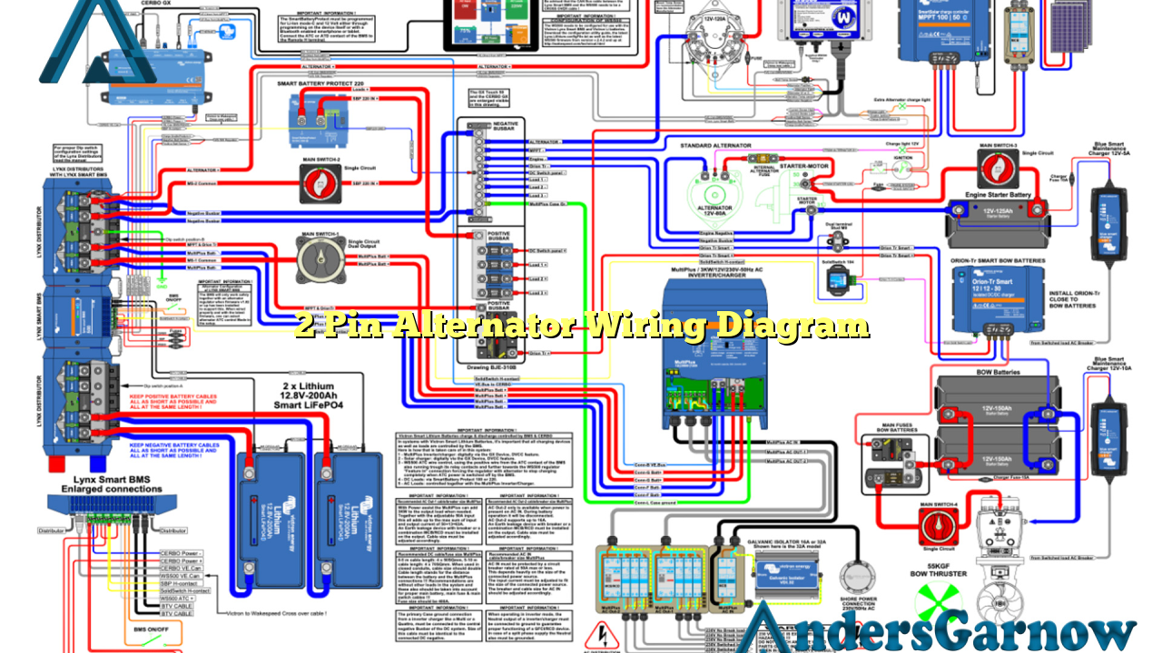
Hello and welcome to our comprehensive guide on the 2 pin alternator wiring diagram. In this article, we will discuss the various aspects of the 2 pin alternator wiring diagram, its advantages, disadvantages, and provide detailed explanations for each subheading.
Subheading 1: Understanding the Basics of a 2 Pin Alternator Wiring Diagram
Before we dive into the specifics, let’s first understand the basics of a 2 pin alternator wiring diagram. The 2 pin alternator is a type of alternator commonly used in automotive applications. It consists of two pins, namely the positive and negative pins, which are responsible for the electrical connections.
Subheading 2: Advantages of a 2 Pin Alternator Wiring Diagram
The 2 pin alternator wiring diagram offers several advantages. Firstly, it is relatively simple and easy to understand, making it suitable for both beginners and experienced individuals. Additionally, the 2 pin alternator wiring diagram provides a clear and concise representation of the electrical connections, ensuring accurate installation and troubleshooting.
Subheading 3: Disadvantages of a 2 Pin Alternator Wiring Diagram
While the 2 pin alternator wiring diagram has its advantages, it also has a few drawbacks. One major disadvantage is its limited compatibility. The 2 pin alternator wiring diagram may not be suitable for all alternator models, especially those with complex electrical systems. It is crucial to ensure compatibility before proceeding with the wiring.
Subheading 4: Detailed Explanation of the Wiring Connections
Now let’s delve into the detailed explanation of the wiring connections in a 2 pin alternator. The positive pin, often denoted by a (+) symbol, is connected to the battery’s positive terminal. This connection ensures the flow of electrical current from the alternator to the battery, charging it during operation.
The negative pin, represented by a (-) symbol, is connected to the vehicle’s ground or chassis. This connection completes the circuit and allows the electrical current to return to the alternator, ensuring a continuous flow of power.
Subheading 5: Alternative Wiring Methods for a 2 Pin Alternator
While the 2 pin alternator wiring diagram is commonly used, there are alternative wiring methods available. One alternative is the use of a voltage regulator, which regulates the voltage output of the alternator. This method provides more control over the charging process and can be beneficial in specific applications.
Subheading 6: Complete Wiring Diagram Table
| Pin | Connection |
|---|---|
| Positive | Battery’s positive terminal |
| Negative | Vehicle’s ground or chassis |
Subheading 7: Frequently Asked Questions (FAQ)
Q: Can I use the 2 pin alternator wiring diagram for any vehicle?
A: The 2 pin alternator wiring diagram is generally suitable for most automotive applications. However, it is essential to check the compatibility of your alternator model before proceeding with the wiring.
Q: Is the 2 pin alternator wiring diagram applicable to both positive and negative ground systems?
A: Yes, the 2 pin alternator wiring diagram is compatible with both positive and negative ground systems. Ensure that you connect the negative pin to the appropriate ground or chassis point.
Conclusion
In conclusion, the 2 pin alternator wiring diagram is a widely used and relatively simple method for connecting an alternator in automotive applications. It offers advantages such as simplicity and clear representation of connections. However, it may have limitations in compatibility. Always ensure compatibility and follow the wiring diagram accurately for a successful installation.

