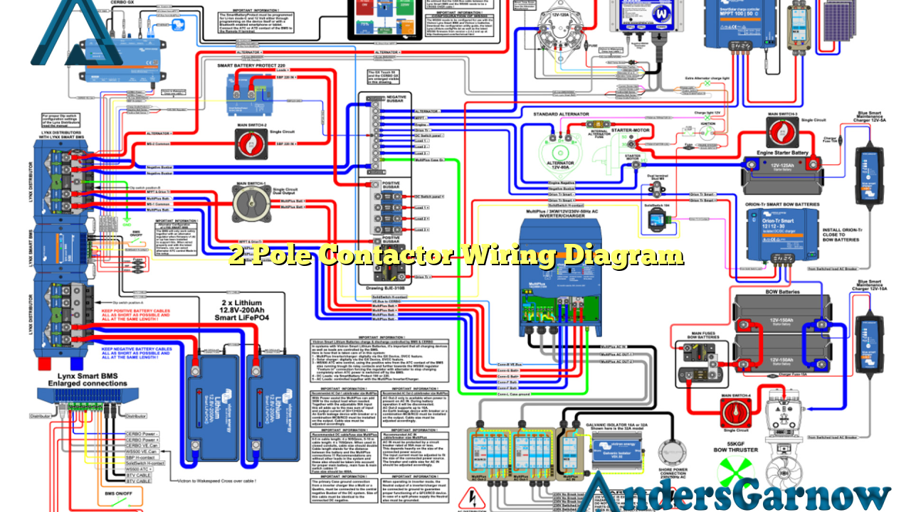
Hello readers! Today, we will be discussing the topic of the 2 pole contactor wiring diagram. Contactor wiring diagrams are essential for understanding and installing electrical components in various systems. In this article, we will explore the details of a 2 pole contactor wiring diagram, its advantages, disadvantages, and alternative options. So, let’s dive right in!
Subheading 1: Understanding a 2 Pole Contactor Wiring Diagram
In electrical systems, a contactor is an electromechanical switch that is used to control the flow of electricity. A 2 pole contactor consists of two separate circuits or poles that can be controlled independently. The wiring diagram of a 2 pole contactor illustrates how these poles are connected to various electrical components.
A typical 2 pole contactor has six terminals, including the coil terminals, main power terminals, and auxiliary control terminals. The coil terminals are where the control voltage is applied to activate the contactor. The main power terminals are used to connect the contactor to the power source and load. The auxiliary control terminals are used for additional control functions, such as motor interlocks or signaling devices.
Subheading 2: Advantages of Using a 2 Pole Contactor Wiring Diagram
There are several advantages to using a 2 pole contactor wiring diagram:
- Compact Design: A 2 pole contactor takes up less space compared to other contactor configurations, making it suitable for applications with limited space.
- Cost-Effective: 2 pole contactors are generally less expensive than contactors with more poles, making them a budget-friendly option.
- Efficient Control: The independent control of each pole allows for efficient operation and flexibility in controlling different electrical components.
Subheading 3: Disadvantages of Using a 2 Pole Contactor Wiring Diagram
While there are advantages, it is also important to consider the disadvantages of using a 2 pole contactor wiring diagram:
- Limited Control: With only two poles, a 2 pole contactor may not be suitable for applications that require control of multiple electrical components.
- Reduced Redundancy: In critical systems, having multiple poles provides redundancy in case of a contactor failure. However, a 2 pole contactor does not offer this redundancy.
- Complexity: Wiring a 2 pole contactor can be more complex compared to single pole contactors, requiring careful attention to ensure proper connections.
Subheading 4: Alternative Options for Contactor Wiring
If a 2 pole contactor is not suitable for your application, there are alternative options available:
- 3 Pole Contactor: A 3 pole contactor provides an additional pole for controlling more electrical components, offering increased flexibility.
- 4 Pole Contactor: Similar to the 3 pole contactor, a 4 pole contactor provides even more control options for complex electrical systems.
- Motor Starters: In some cases, motor starters with built-in contactors may be a more convenient option, especially for motor control applications.
Subheading 5: 2 Pole Contactor Wiring Diagram – Complete Information
Below is a comprehensive table providing all the necessary information for a 2 pole contactor wiring diagram:
| Terminal | Description |
|---|---|
| Coil Terminal 1 | Connection for the first terminal of the control voltage coil |
| Coil Terminal 2 | Connection for the second terminal of the control voltage coil |
| Main Power Terminal 1 | Connection for the first terminal of the power source |
| Main Power Terminal 2 | Connection for the second terminal of the power source |
| Load Terminal 1 | Connection for the first terminal of the load |
| Load Terminal 2 | Connection for the second terminal of the load |
Subheading 6: FAQ
Here are some frequently asked questions regarding 2 pole contactor wiring diagrams:
Q: Can I use a 2 pole contactor for controlling a three-phase motor?
A: Yes, a 2 pole contactor can be used for controlling a three-phase motor. However, additional components, such as overload relays, may be required for motor protection.
Q: How do I determine the coil voltage for a 2 pole contactor?
A: The coil voltage of a contactor should match the control voltage of the system. Consult the electrical specifications or a professional to determine the appropriate coil voltage.
Q: Can I connect multiple loads to a 2 pole contactor?
A: Yes, you can connect multiple loads to a 2 pole contactor. However, ensure that the total load current does not exceed the contactor’s rated current.
Conclusion
In conclusion, a 2 pole contactor wiring diagram is an essential tool for understanding and installing electrical components in various systems. While it offers advantages such as compact design and cost-effectiveness, it also has limitations in terms of control options and redundancy. If a 2 pole contactor is not suitable, alternative options such as 3 pole contactors or motor starters can be considered. It is crucial to refer to the provided table and consult professionals when wiring a 2 pole contactor to ensure proper connections and safe operation.

