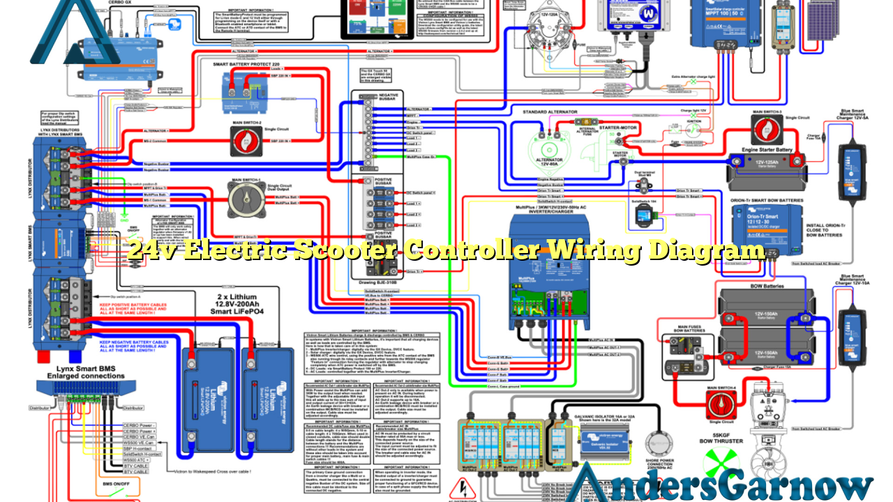
Hello and welcome to our article on the 24v electric scooter controller wiring diagram. In this detailed guide, we will provide you with all the information you need to understand and implement the wiring diagram for a 24v electric scooter controller. Whether you are a beginner or an experienced electric scooter enthusiast, this article will help you navigate through the complexities of the wiring diagram and ensure a successful installation.
1. Understanding the Basics
Before diving into the wiring diagram, let’s first understand the basics of a 24v electric scooter controller. The controller is responsible for regulating the power flow from the battery to the motor, ensuring smooth acceleration and control. It acts as the brain of the scooter, receiving input signals from the throttle and brake, and adjusting the power output accordingly.
However, it’s important to note that different scooter models might have slight variations in their wiring configurations. Therefore, it is crucial to refer to the specific wiring diagram provided by the manufacturer for your scooter model.
2. Components Needed
To successfully wire a 24v electric scooter controller, you will need the following components:
| Component | Description |
|---|---|
| Battery | A 24v battery to power the scooter. |
| Controller | The 24v electric scooter controller that regulates power flow. |
| Motor | The electric motor that drives the scooter. |
| Throttle | The throttle mechanism that controls the scooter’s speed. |
| Brake | The brake mechanism that controls the scooter’s stopping power. |
| Wiring Harness | The set of wires and connectors to connect all the components. |
3. Wiring Diagram
Now, let’s delve into the wiring diagram for a 24v electric scooter controller. Please refer to the table below for a detailed breakdown of the connections:
| Wire Color | Connection |
|---|---|
| Red | Connects the positive terminal of the battery to the controller’s positive terminal. |
| Black | Connects the negative terminal of the battery to the controller’s negative terminal. |
| Green | Connects the throttle’s signal wire to the controller’s throttle input. |
| Yellow | Connects the brake’s signal wire to the controller’s brake input. |
| Blue | Connects the motor’s positive wire to the controller’s positive motor terminal. |
| White | Connects the motor’s negative wire to the controller’s negative motor terminal. |
It is essential to double-check the wiring connections and ensure they are secure before testing the scooter.
4. Advantages of a 24v Electric Scooter Controller
A 24v electric scooter controller offers several advantages:
- Efficient power regulation for smooth acceleration and control.
- Enhanced battery life due to optimized power flow.
- Compatibility with various scooter models that operate on a 24v system.
- Improved safety features, such as electronic braking systems.
- Easy installation and wiring process.
5. Disadvantages of a 24v Electric Scooter Controller
While a 24v electric scooter controller has numerous benefits, it also has a few drawbacks:
- Lower top speed compared to higher voltage controllers.
- Reduced torque, especially when tackling uphill terrains.
- Limitations in customization options due to the specific voltage requirement.
6. Alternative Wiring Options
If you are looking for alternative wiring options for your 24v electric scooter controller, you might consider:
- Adding an additional battery in series to increase the voltage and enhance the scooter’s performance.
- Implementing a higher voltage controller for faster acceleration and higher top speed.
- Incorporating a regenerative braking system to improve energy efficiency.
7. Frequently Asked Questions (FAQ)
Q: Can I use a higher voltage battery with a 24v electric scooter controller?
A: It is not recommended to use a higher voltage battery with a 24v controller as it can damage the controller and other components.
Q: How can I troubleshoot wiring issues with my electric scooter controller?
A: Start by checking all the wiring connections for secureness and correctness. Ensure that all wires are properly insulated to prevent short circuits. If the issue persists, consult a professional or refer to the manufacturer’s troubleshooting guide.
Conclusion
In conclusion, understanding and implementing the 24v electric scooter controller wiring diagram is essential for a successful installation and optimal performance. By following the provided wiring connections and considering the alternative options, you can customize and enhance your electric scooter experience. Remember to prioritize safety and double-check all connections before testing the scooter. Enjoy your electric scooter adventures!

