Hello readers! In this article, we will delve into the intriguing world of 250cc 6 pin CDI wiring diagrams. Whether you are a motorcycle enthusiast, an aspiring mechanic, or simply curious about the inner workings of these powerful machines, this comprehensive guide will provide you with the knowledge you seek. So let’s dive in!
1. Understanding the Basics of a 250cc 6 Pin CDI Wiring Diagram
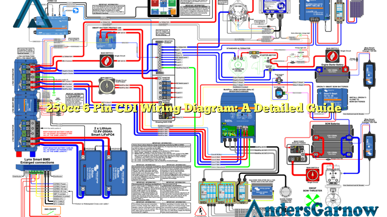
A 250cc 6 pin CDI wiring diagram is a visual representation of the electrical connections and circuitry involved in the ignition system of a 250cc motorcycle. It showcases the various components, such as the CDI unit, ignition coil, and spark plug, and illustrates how they are interconnected to ensure proper functioning of the ignition system.
By referring to the wiring diagram, you can gain a deeper understanding of how electricity flows within your motorcycle’s ignition system, enabling you to troubleshoot issues, make modifications, or even build your own custom wiring setup.
2. Benefits of a 250cc 6 Pin CDI Wiring Diagram
There are several advantages to familiarizing yourself with a 250cc 6 pin CDI wiring diagram:
– Troubleshooting: When faced with ignition-related problems, the wiring diagram acts as a valuable tool in identifying faulty connections or components.
– Modifications: If you plan on upgrading or customizing your motorcycle’s ignition system, the wiring diagram provides a blueprint for implementing these changes.
– Understanding Functionality: By studying the diagram, you can grasp how each component contributes to the overall ignition process, enhancing your knowledge of motorcycle mechanics.
3. Key Components in a 250cc 6 Pin CDI Wiring Diagram
A typical 250cc 6 pin CDI wiring diagram includes the following components:
| Component | Description |
|---|---|
| CDI Unit | The Capacitor Discharge Ignition unit controls the ignition timing and spark generation. |
| Ignition Coil | Converts the low voltage from the battery into a high voltage current, which is then sent to the spark plug. |
| Spark Plug | Creates the spark that ignites the air-fuel mixture in the combustion chamber, resulting in engine combustion. |
| Battery | Provides the electrical energy required to power the ignition system. |
| Stator | Generates alternating current (AC) from the rotation of the engine’s crankshaft. |
| Rectifier | Converts the AC voltage from the stator into direct current (DC) to charge the battery and power other electrical components. |
4. Step-by-Step Guide to Wiring a 250cc 6 Pin CDI
Now, let’s walk through the process of wiring a 250cc 6 pin CDI:
Step 1: Gather the necessary tools and materials, including the wiring diagram, wire cutters/strippers, electrical tape, and a soldering iron.
Step 2: Study the wiring diagram to understand the color codes and connections of each wire.
Step 3: Disconnect the battery to prevent any electrical mishaps.
Step 4: Begin by connecting the CDI unit to the ignition coil using the designated wires.
Step 5: Connect the ignition coil to the spark plug using a high-tension wire.
Step 6: Ensure all connections are secure and insulated using electrical tape or heat shrink tubing.
Step 7: Reconnect the battery and test the ignition system.
5. Common Issues and Troubleshooting
Despite their reliability, 250cc 6 pin CDI systems can encounter problems. Here are a few common issues and their potential solutions:
– No Spark: Check the ignition coil, spark plug, and wiring connections for any faults. Ensure proper grounding and verify that the CDI unit is receiving power.
– Weak Spark: Inspect the ignition coil and spark plug for signs of wear or damage. Replace if necessary.
– Intermittent Spark: Examine the wiring connections and CDI unit for loose or corroded contacts. Clean or tighten as needed.
– Excessive Heat: Overheating may indicate a faulty CDI unit or inadequate cooling. Replace the CDI unit and ensure proper ventilation.
6. Alternatives for 250cc 6 Pin CDI Wiring Diagrams
While a 250cc 6 pin CDI wiring diagram provides detailed information specific to this particular model, there are alternative resources available:
– Online Forums: Engage with fellow motorcycle enthusiasts on online forums dedicated to your motorcycle’s make and model. These communities often share valuable wiring diagrams and troubleshooting tips.
– Manufacturer’s Manuals: Reference the official manual provided by the motorcycle manufacturer. It typically includes wiring diagrams and detailed instructions specific to your model.
– Professional Assistance: If you are unsure or uncomfortable with wiring modifications, consult a professional motorcycle mechanic or electrician. They possess the expertise to guide you through the process safely.
Conclusion
250cc 6 pin CDI wiring diagrams serve as indispensable tools for motorcycle enthusiasts and mechanics alike. By understanding the intricacies of the wiring diagram, you can troubleshoot issues, make modifications, and gain a deeper appreciation for your motorcycle’s ignition system. Remember to always prioritize safety and consult professional assistance when needed. Happy riding!

