Hello and welcome to this informative article on 3 wire bilge pump wiring diagram. In this article, we will discuss the various aspects of wiring a bilge pump with 3 wires, including its advantages, disadvantages, and alternative wiring options. So, let’s dive in!
1. Understanding the Basics of a Bilge Pump
Before we delve into the wiring diagram, it is important to understand the basics of a bilge pump. A bilge pump is an essential component of a boat’s plumbing system that helps to remove water from the bilge area, keeping the boat afloat and free from any potential damage.
2. The Importance of Proper Wiring
Proper wiring of a bilge pump is crucial to ensure its optimal performance and safety. A correctly wired bilge pump ensures that it operates efficiently, automatically activating when water levels rise and deactivating once the water is pumped out.
3. The 3 Wire Bilge Pump Wiring Diagram
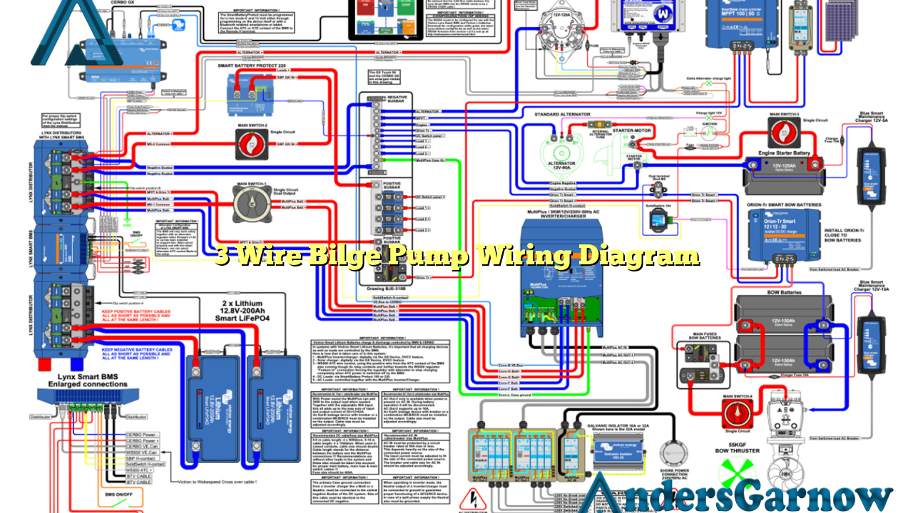
The 3 wire bilge pump wiring diagram consists of three wires – positive, negative, and an additional wire for the float switch. The positive wire connects to the boat’s battery or power source, while the negative wire connects to the boat’s ground or negative terminal.
The additional wire is connected to the float switch, which is responsible for sensing the water level in the bilge area. When the water level rises, the float switch activates the pump, and when the water is pumped out, it deactivates the pump.
Advantages of the 3 Wire Bilge Pump Wiring Diagram
The 3 wire bilge pump wiring diagram offers several advantages:
- Automatic Operation: The inclusion of a float switch allows for automatic operation, eliminating the need for manual control.
- Efficient Water Removal: The automatic activation of the pump ensures quick and efficient water removal from the bilge area.
- Prevents Overloading: The float switch prevents the pump from running continuously, preventing motor burnout and overloading.
Disadvantages of the 3 Wire Bilge Pump Wiring Diagram
While the 3 wire bilge pump wiring diagram has its advantages, it also has a few limitations:
- Complex Wiring: The inclusion of an additional wire for the float switch adds complexity to the wiring process.
- Higher Installation Cost: The additional components required for the float switch can increase the overall installation cost.
Alternative Wiring Options
If the 3 wire bilge pump wiring diagram seems too complex or costly, there are alternative wiring options available:
- 2 Wire Bilge Pump Wiring Diagram: This simpler wiring diagram eliminates the need for a float switch but requires manual control of the pump.
- Smart Bilge Pump Switch: This innovative solution combines automated operation with simplicity, allowing for easy installation and control.
3 Wire Bilge Pump Wiring Diagram – Complete Information
| Wire | Color | Function |
|---|---|---|
| Positive | Red | Connects to boat’s battery or power source |
| Negative | Black | Connects to boat’s ground or negative terminal |
| Float Switch | White | Connects to the float switch for automatic activation |
Frequently Asked Questions (FAQ)
Q: Can I use a 2 wire bilge pump instead of a 3 wire bilge pump?
A: Yes, you can use a 2 wire bilge pump, but keep in mind that it will require manual control.
Q: What if the float switch malfunctions?
A: Regular maintenance and inspection are essential to ensure the proper functioning of the float switch. If it malfunctions, it should be replaced promptly.
In Conclusion
In conclusion, the 3 wire bilge pump wiring diagram offers automatic operation and efficient water removal, but it can be more complex and costly compared to alternative wiring options. Understanding the wiring diagram and choosing the right option for your boat’s needs is crucial for the optimal performance of the bilge pump.

