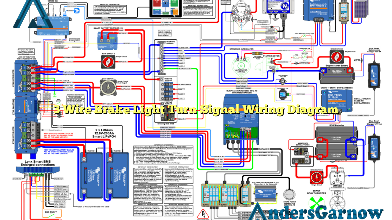
Hello readers! In this article, we will discuss the 3 wire brake light turn signal wiring diagram, a crucial aspect of vehicle safety and functionality. Understanding this diagram will enable you to properly wire your brake lights and turn signals, ensuring a safe driving experience. So, let’s dive right in!
1. What is a 3 Wire Brake Light Turn Signal Wiring Diagram?
A 3 wire brake light turn signal wiring diagram is a visual representation of how the brake lights and turn signals are connected in a vehicle’s electrical system. It illustrates the flow of electricity and the connections between the various components involved.
The diagram typically includes three wires: a power wire, a ground wire, and a signal wire. The power wire carries the electrical current to the lights, the ground wire provides a return path for the current, and the signal wire controls the activation of the brake lights and turn signals.
2. Components of a 3 Wire Brake Light Turn Signal Wiring Diagram
The main components included in a 3 wire brake light turn signal wiring diagram are:
| Component | Description |
|---|---|
| Power Source | Provides electrical current to the brake lights and turn signals. |
| Brake Light Switch | Activates the brake lights when the brake pedal is pressed. |
| Turn Signal Switch | Controls the activation of the turn signals. |
| Brake Light Bulbs | Illuminate when the brake pedal is pressed, indicating the vehicle is slowing down or stopping. |
| Turn Signal Bulbs | Flash to indicate the intention of the driver to turn left or right. |
| Ground Connection | Provides a return path for the electrical current. |
3. Wiring Diagram and Connections
The wiring diagram for a 3 wire brake light turn signal system may vary depending on the specific vehicle make and model. However, the general connections remain the same.
The power wire is connected to the positive terminal of the power source, such as the battery. The ground wire is connected to the vehicle’s chassis or a dedicated ground point. The signal wire is connected to the brake light switch and the turn signal switch.
When the brake pedal is pressed, the brake light switch completes the circuit and activates the brake lights. When the turn signal switch is engaged, it sends a signal to the corresponding turn signal bulbs, causing them to flash.
4. Advantages of a 3 Wire Brake Light Turn Signal Wiring Diagram
The 3 wire brake light turn signal wiring diagram provides several advantages, including:
- Safety: Properly wiring the brake lights and turn signals ensures that other drivers can easily see your intentions on the road, reducing the risk of accidents.
- Functionality: A well-connected wiring system ensures the smooth operation of the brake lights and turn signals, allowing for clear communication with other drivers.
- Easy Troubleshooting: Having a wiring diagram at hand makes it easier to diagnose and fix any electrical issues related to the brake lights and turn signals.
5. Disadvantages of a 3 Wire Brake Light Turn Signal Wiring Diagram
While the 3 wire brake light turn signal wiring diagram offers numerous benefits, it also has a few disadvantages:
- Complexity: Understanding and properly interpreting the wiring diagram may be challenging for individuals without prior electrical knowledge.
- Potential for Errors: Incorrectly connecting the wires can lead to malfunctioning brake lights and turn signals, compromising vehicle safety.
- Vehicle-Specific Variations: Different vehicle makes and models may have slight variations in their wiring diagrams, requiring specific knowledge or reference to the vehicle’s manual.
6. Alternative Wiring Methods
Aside from the 3 wire brake light turn signal wiring diagram, there are alternative methods to achieve similar functionality. One such method is using a 4 wire system, where a separate wire is dedicated to the brake lights and turn signals.
This alternative wiring method simplifies the connections and allows for easier troubleshooting. However, it may require additional wiring and components, making the installation more complex.
Conclusion
In conclusion, understanding the 3 wire brake light turn signal wiring diagram is crucial for ensuring the safety and functionality of your vehicle’s electrical system. By following the proper connections and utilizing the diagram, you can wire your brake lights and turn signals effectively.
Remember to refer to the specific wiring diagram for your vehicle make and model, as slight variations may exist. If you are unsure or uncomfortable with the wiring process, it is always recommended to consult a professional automotive technician.
Drive safely and stay informed about your vehicle’s electrical system!

