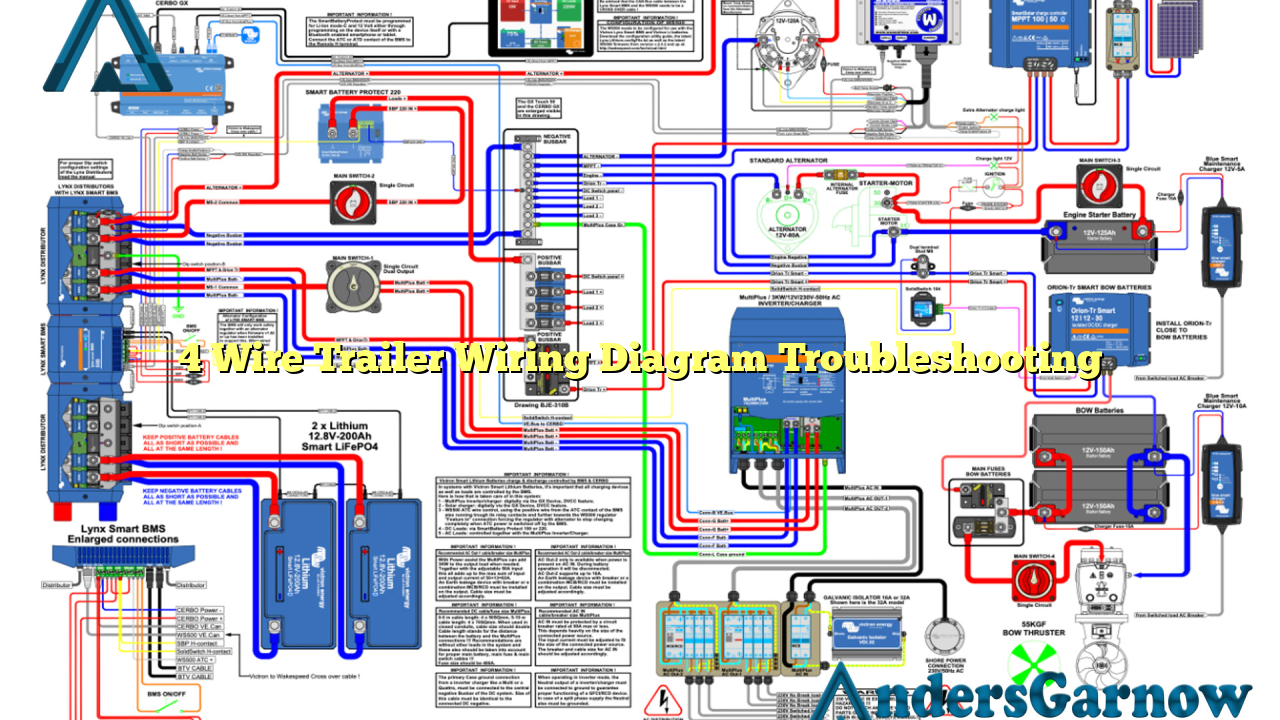
Hello, dear readers! Today, we will discuss a topic that is crucial for anyone who owns a trailer – the 4 wire trailer wiring diagram troubleshooting. Whether you are a seasoned trailer owner or a newbie, understanding the wiring system is essential for safe and efficient towing. In this article, we will explore the ins and outs of the 4 wire trailer wiring diagram, its troubleshooting aspects, and provide alternative solutions for your convenience.
1. Understanding the Basics of 4 Wire Trailer Wiring Diagram
Before we delve into troubleshooting, let’s first understand what the 4 wire trailer wiring diagram entails. The 4 wire system consists of four color-coded wires: brown, yellow, green, and white. Each wire serves a specific purpose in the electrical system of your trailer. The brown wire is for the tail lights, the yellow wire is for the left turn signal and brake light, the green wire is for the right turn signal and brake light, and the white wire is for the ground connection.
By following the 4 wire trailer wiring diagram, you can ensure that the electrical connections between your trailer and towing vehicle are properly established, allowing for the smooth operation of all the necessary lights and signals.
2. Common Issues and Troubleshooting
Despite the simplicity of the 4 wire trailer wiring system, issues can arise that require troubleshooting. Let’s examine some common problems and their solutions:
Issue 1: No Power to Trailer Lights
This issue is often caused by a blown fuse or a loose connection. Check the fuse box in your towing vehicle and replace any blown fuses. Ensure that all connections are secure and free of corrosion. If the problem persists, consult a professional for further assistance.
Issue 2: Dim or Flickering Lights
Dim or flickering lights can be a result of a poor ground connection. Inspect the white wire connection and ensure it is securely attached to a clean metal surface. Clean any rust or debris that may hinder the proper grounding.
Issue 3: Inconsistent Brake or Turn Signal Lights
If your brake or turn signal lights are not functioning properly, it could indicate a faulty bulb or socket. Replace any burnt-out bulbs or damaged sockets to restore the functionality of these lights.
Issue 4: Crossed Wires
In some cases, the wires may be improperly connected, causing confusion and malfunction. Carefully examine the 4 wire trailer wiring diagram and ensure that each wire is connected to the correct corresponding terminal. Crossed wires can lead to unpredictable behavior of the lights and signals.
3. Alternative Solutions
While the 4 wire trailer wiring diagram is widely used, there are alternative solutions available for those seeking different wiring configurations. One popular alternative is the 7 wire system, which provides additional functionality such as electric brakes and auxiliary power. However, it is important to note that utilizing alternative wiring systems may require modifications to both the trailer and the towing vehicle. Consult a professional or refer to specific wiring guides for your desired alternative solution.
4 Wire Trailer Wiring Diagram Troubleshooting Table
| Issue | Cause | Solution |
|---|---|---|
| No Power to Trailer Lights | Blown fuse or loose connection | Replace blown fuses and secure connections |
| Dim or Flickering Lights | Poor ground connection | Ensure secure grounding on clean metal surface |
| Inconsistent Brake or Turn Signal Lights | Faulty bulb or socket | Replace burnt-out bulbs or damaged sockets |
| Crossed Wires | Improper wire connections | Refer to the wiring diagram and ensure correct connections |
Frequently Asked Questions (FAQ)
Q: Can I use the 4 wire trailer wiring diagram for a 5 wire trailer?
A: No, the 4 wire trailer wiring diagram is specific to trailers with four electrical connections. If you have a 5 wire trailer, you will need a different wiring diagram that accommodates the additional wire.
Q: How do I test the continuity of the wires?
A: To test the continuity of the wires, use a multimeter set to the continuity mode. Connect one probe to a wire’s exposed metal end and the other probe to a known ground. If the multimeter beeps or shows a reading close to zero ohms, it indicates that the wire has continuity.
In Conclusion
In conclusion, understanding the 4 wire trailer wiring diagram troubleshooting is essential for safe and efficient towing. By familiarizing yourself with the basics, common issues, and alternative solutions, you can ensure that your trailer’s electrical system functions properly. Remember to always consult a professional if you encounter complex wiring problems or if you are unsure about any aspect of the troubleshooting process. Safe travels!

