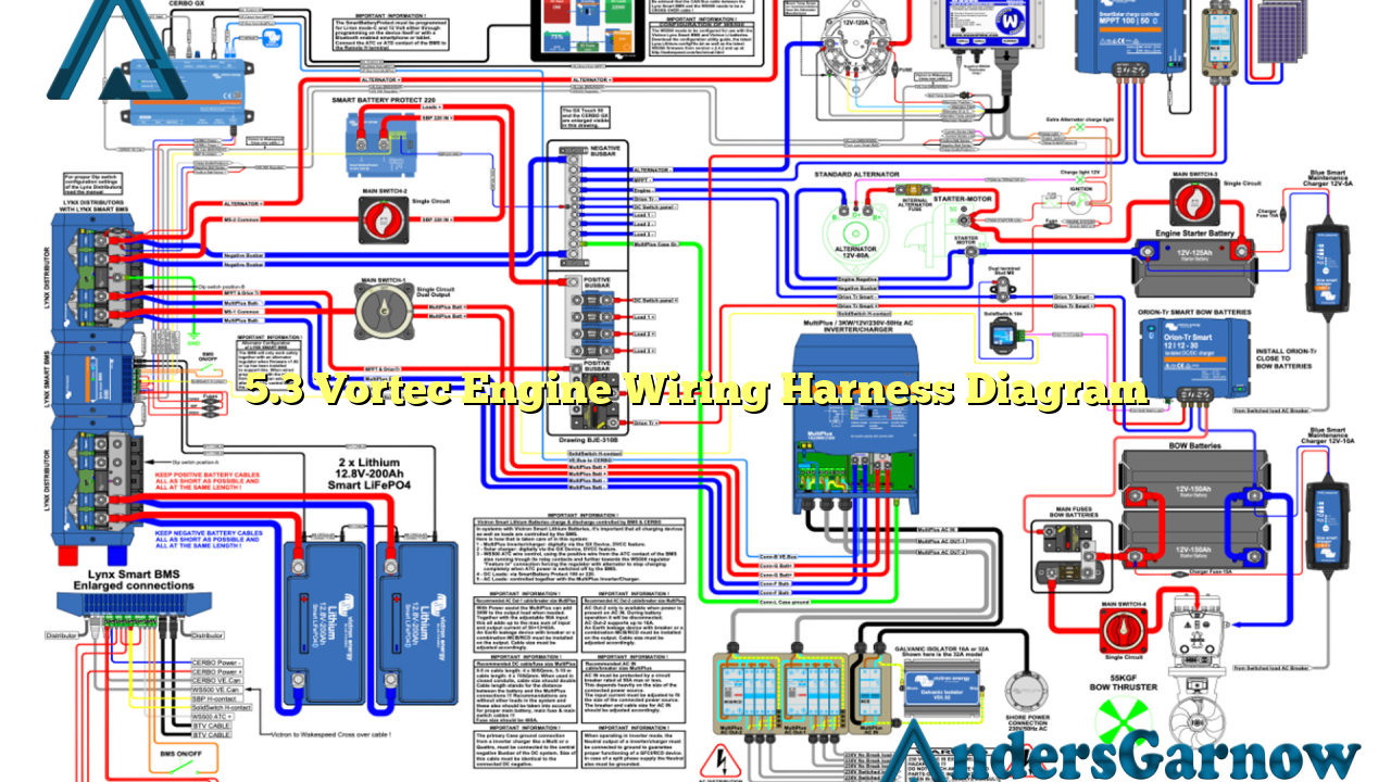
Hello and welcome to our informative article on the 5.3 Vortec engine wiring harness diagram. In this comprehensive guide, we will explore the various aspects of the wiring harness diagram for the 5.3 Vortec engine, providing you with all the necessary information you need to understand and work with this essential component of your engine. So, let’s dive right in!
1. Understanding the Basics of a Wiring Harness Diagram
Before we delve into the specifics of the 5.3 Vortec engine wiring harness diagram, let’s first understand the basics of what a wiring harness diagram is and why it is crucial for your engine. A wiring harness diagram is a visual representation of the electrical connections and wiring within an engine. It provides a detailed overview of the various wires, connectors, and components, allowing technicians and enthusiasts to understand the engine’s electrical system.
The 5.3 Vortec engine wiring harness diagram is particularly essential for troubleshooting electrical issues, performing engine swaps, or modifying the engine’s electrical system. It ensures that all connections are correctly made and provides a roadmap for diagnosing and fixing any problems that may arise.
2. Components of the 5.3 Vortec Engine Wiring Harness Diagram
The 5.3 Vortec engine wiring harness diagram comprises several key components that work together to ensure the engine’s electrical system operates smoothly. These components include:
| Component | Description |
|---|---|
| ECM/PCM | The Engine Control Module or Powertrain Control Module, which controls various engine functions. |
| Ignition Coil | Responsible for generating the high voltage required to ignite the fuel mixture in the engine cylinders. |
| Injectors | Deliver precise amounts of fuel into the engine cylinders based on signals from the ECM/PCM. |
| Sensors | Includes various sensors such as the Mass Air Flow sensor, Oxygen sensor, and Coolant Temperature sensor, which provide crucial data to the ECM/PCM for optimal engine performance. |
| Fuel Pump | Supplies fuel from the fuel tank to the injectors. |
| Coil Packs | Converts the low voltage from the ignition coil into a high voltage required for spark plug ignition. |
These components, along with numerous connectors and wiring, form the intricate network of the 5.3 Vortec engine wiring harness diagram.
3. Advantages of the 5.3 Vortec Engine Wiring Harness Diagram
The 5.3 Vortec engine wiring harness diagram offers several advantages, making it an invaluable resource for engine enthusiasts and technicians. Some of the key advantages include:
- Easy Troubleshooting: With the wiring harness diagram, troubleshooting electrical issues becomes more accessible as it provides a visual representation of the engine’s electrical connections.
- Accurate Modifications: When modifying the engine’s electrical system, the diagram ensures that the correct connections are made, reducing the risk of errors.
- Efficient Repairs: Repairing faulty electrical connections or replacing components becomes more efficient with the guidance of the wiring harness diagram.
- Enhanced Understanding: The diagram allows enthusiasts to gain a deeper understanding of the engine’s electrical system, empowering them to make informed decisions and modifications.
4. Limitations of the 5.3 Vortec Engine Wiring Harness Diagram
While the 5.3 Vortec engine wiring harness diagram offers numerous advantages, it is essential to consider its limitations as well. Some of the limitations include:
- Complexity: The wiring harness diagram can be overwhelming for beginners due to the complexity of the engine’s electrical system.
- Specificity: The diagram is specific to the 5.3 Vortec engine and may not be directly applicable to other engine models.
- Updates: As technology advances, there may be updates or revisions to the wiring harness diagram. It is crucial to ensure you have the latest version for accurate information.
5. Alternatives to the 5.3 Vortec Engine Wiring Harness Diagram
If you are unable to access or understand the 5.3 Vortec engine wiring harness diagram, there are alternative resources you can explore. These alternatives include:
- Manufacturer’s Documentation: The engine’s manufacturer may provide detailed documentation on the wiring harness diagram, including step-by-step instructions and illustrations.
- Online Forums and Communities: Engaging with online forums and communities dedicated to engine enthusiasts can provide valuable insights and guidance on wiring harness diagrams.
- Professional Assistance: Seeking assistance from a professional mechanic or technician with experience in the 5.3 Vortec engine can ensure accurate wiring and troubleshooting.
Conclusion
In conclusion, the 5.3 Vortec engine wiring harness diagram is a vital tool for understanding and working with the engine’s electrical system. It provides a detailed overview of the various components, connectors, and wiring, enabling efficient troubleshooting, modifications, and repairs. While it offers numerous advantages, it is essential to be aware of its limitations and explore alternative resources when needed. By utilizing the wiring harness diagram effectively, you can ensure optimal performance and reliability of your 5.3 Vortec engine.
Frequently Asked Questions (FAQ)
Q: Can I use the 5.3 Vortec engine wiring harness diagram for other engine models?
A: The 5.3 Vortec engine wiring harness diagram is specifically designed for the 5.3 Vortec engine. While certain principles may be applicable to other engines, it is recommended to refer to the specific wiring diagram for each engine model.
Q: Where can I find the latest version of the 5.3 Vortec engine wiring harness diagram?
A: The latest version of the wiring harness diagram can usually be obtained from the engine’s manufacturer or authorized dealers. Additionally, online resources and forums dedicated to engine enthusiasts may also provide updated versions of the diagram.
Q: How can I ensure accurate connections when using the wiring harness diagram?
A: It is crucial to carefully follow the instructions provided in the wiring harness diagram. Double-checking each connection and referring to additional resources, such as the manufacturer’s documentation, can help ensure accurate connections.

