Hello, dear readers, and welcome to this informative article about circuit diagrams. In the world of electronics, circuit diagrams serve as the blueprint for designing, building, and troubleshooting electrical circuits. They provide a visual representation of the connections and components involved in a circuit, allowing engineers, technicians, and hobbyists to understand and work with complex electrical systems. In this article, we will explore the various aspects of circuit diagrams, their advantages, disadvantages, and alternative methods. So, let’s dive in!
1. What is a Circuit Diagram?
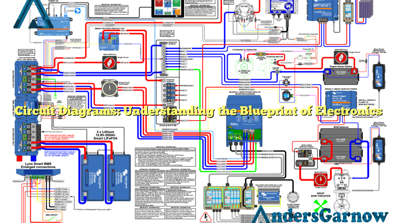
A circuit diagram, also known as a schematic diagram or electrical diagram, is a visual representation of an electrical circuit. It uses standardized symbols to depict the connections and components of a circuit, such as resistors, capacitors, transistors, and power sources. Circuit diagrams are essential tools for understanding how a circuit works and for designing and troubleshooting electrical systems.
2. Advantages of Circuit Diagrams
Circuit diagrams offer several advantages that make them indispensable in the field of electronics:
- Clarity and Simplicity: Circuit diagrams provide a clear and concise representation of complex electrical circuits, making it easier to understand their structure and functionality.
- Universal Language: Circuit diagrams use standardized symbols that are recognized and understood worldwide, facilitating communication and collaboration among engineers and technicians.
- Compactness: Circuit diagrams condense a large amount of information into a compact format, allowing engineers to visualize an entire circuit on a single page.
- Easy Modification: Circuit diagrams can be easily modified and updated to accommodate changes in the circuit design or to troubleshoot issues.
- Efficient Troubleshooting: Circuit diagrams enable technicians to identify and isolate faulty components or connections quickly, speeding up the troubleshooting process.
3. Disadvantages of Circuit Diagrams
While circuit diagrams offer numerous advantages, they also have some limitations:
- Steep Learning Curve: Understanding and interpreting circuit diagrams requires a solid understanding of electrical concepts and familiarity with the standardized symbols used in the diagrams.
- Complexity: Circuit diagrams can become increasingly complex as the circuits they represent become more intricate, making them challenging to comprehend for beginners or those without sufficient technical knowledge.
- Limited Real-World Representation: Circuit diagrams provide an abstract representation of a circuit, focusing on its electrical connections rather than the physical layout or appearance of the components.
- Space Constraints: As circuits become larger and more complex, fitting all the components and connections onto a single diagram may become impractical or result in a cluttered and confusing representation.
4. Alternative Methods for Visualizing Circuits
While circuit diagrams are the most commonly used method for visualizing circuits, there are alternative approaches that offer different perspectives:
- Breadboard Prototyping: Breadboards allow engineers and hobbyists to build physical prototypes of circuits using actual components, providing a hands-on approach to circuit design and testing.
- PCB Layouts: Printed Circuit Board (PCB) layouts provide a detailed representation of a circuit’s physical layout, including the placement and interconnections of components on a PCB.
- 3D Modeling: With advancements in computer-aided design (CAD) software, engineers can create 3D models of circuits, offering a realistic visualization of a circuit’s physical appearance and spatial relationships.
5. Circuit Diagram Information Table
| Symbol | Description |
|---|---|
| Resistor | A passive two-terminal electrical component that resists the flow of current. |
| Capacitor | An electronic component that stores and releases electrical energy. |
| Transistor | A semiconductor device used to amplify or switch electronic signals and electrical power. |
| Power Source | A device or system that provides electrical energy to a circuit. |
6. Frequently Asked Questions (FAQ)
Q: Can I create my own circuit diagram?
A: Absolutely! With the help of circuit design software or by hand-drawing, you can create your own circuit diagrams.
Q: Are circuit diagrams only used by professionals?
A: No, circuit diagrams are used by professionals, hobbyists, and anyone involved in electronics to understand, design, and troubleshoot circuits.
Q: Are there different types of circuit diagrams?
A: Yes, there are various types of circuit diagrams, including block diagrams, wiring diagrams, and ladder diagrams, each serving different purposes.
In Conclusion
Circuit diagrams play a crucial role in the world of electronics, providing a visual representation of electrical circuits. Despite their limitations, circuit diagrams offer clarity, universality, and efficiency in understanding, designing, and troubleshooting circuits. Whether you’re an aspiring engineer or a curious hobbyist, mastering the language of circuit diagrams will unlock a world of possibilities in the realm of electronics.
