Hello and welcome to this informative article on connection diagrams. In today’s digital age, where connectivity is paramount, understanding how devices and systems connect is crucial. Whether you are an engineer, a technician, or simply someone interested in the world of technology, this article will provide you with a detailed insight into connection diagrams and their significance in various industries.
1. What is a Connection Diagram?
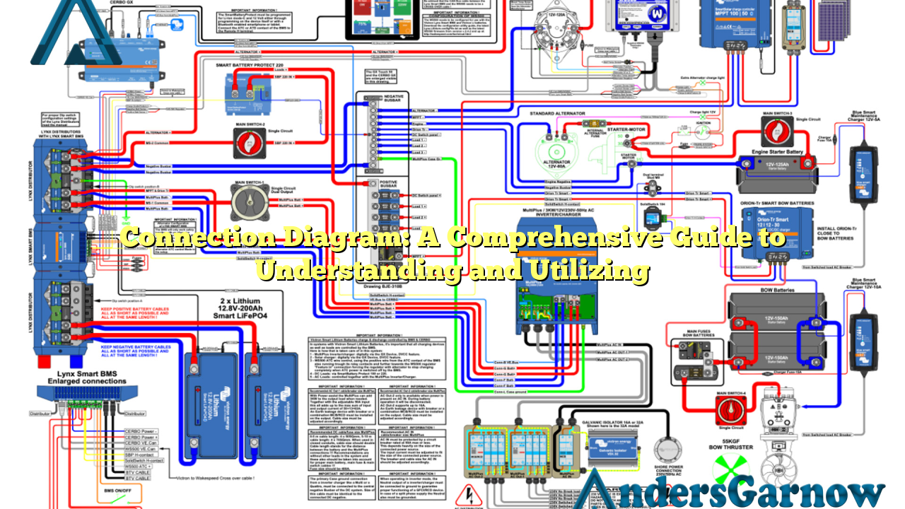
A connection diagram, also known as a wiring diagram or schematic diagram, is a visual representation of how various components or devices are interconnected. It illustrates the physical connections, wiring paths, and relationship between different elements in a system. Connection diagrams are widely used in electrical, electronics, telecommunications, and other related fields to depict complex systems in a simplified manner.
Advantages of Connection Diagrams
Connection diagrams offer several advantages, making them an invaluable tool for professionals and enthusiasts alike. Some key advantages include:
| Advantages | Explanation |
|---|---|
| Clear Visualization | Connection diagrams provide a clear and concise visual representation of complex systems, making it easier to understand and troubleshoot. |
| Troubleshooting Aid | When issues arise, connection diagrams serve as a valuable reference for identifying faulty connections or components. |
| Standardization | Connection diagrams follow standardized symbols and conventions, allowing for universal understanding and interpretation. |
| Efficient Communication | They facilitate effective communication between engineers, technicians, and other stakeholders involved in a project. |
2. Types of Connection Diagrams
Connection diagrams can be categorized into different types based on their applications and industry-specific requirements. The most common types include:
a) Electrical Connection Diagrams
Electrical connection diagrams illustrate the connections and wiring configurations of electrical components and systems. They are extensively used in power distribution, control panels, and building wiring layouts. These diagrams help electricians and engineers understand the flow of electricity and ensure safe and efficient electrical installations.
b) Electronics Connection Diagrams
Electronics connection diagrams focus on the interconnections of electronic components such as transistors, resistors, capacitors, and integrated circuits (ICs). These diagrams are essential in designing and troubleshooting electronic circuits and devices, ranging from simple gadgets to complex computer systems.
c) Network Connection Diagrams
Network connection diagrams depict the connections and relationships between various network devices, such as routers, switches, servers, and client devices. They are used in computer networks, telecommunications, and data centers to assist network administrators in managing and maintaining network infrastructure.
3. Creating a Connection Diagram
Creating a connection diagram requires a systematic approach to ensure accuracy and clarity. Here are the general steps involved:
- Identify the components: Determine the devices or components involved in the system and their respective connections.
- Select the symbols: Choose the appropriate symbols or standardized icons that represent the components accurately.
- Draw the connections: Use lines or arrows to depict the connections between the components. Follow a logical flow from input to output.
- Add labels and annotations: Label the components and connections for easy identification and understanding.
- Review and revise: Double-check the diagram for any errors or inconsistencies. Make revisions as necessary.
Limitations of Connection Diagrams
While connection diagrams are highly beneficial, they do have certain limitations. It’s important to be aware of these limitations to avoid potential pitfalls. Some limitations include:
- Complexity: Connection diagrams may become complex and hard to interpret in highly intricate systems.
- Dynamic Systems: They may not capture the dynamic behavior or real-time changes in certain systems.
- Space Constraints: Limited space may restrict the level of detail that can be included in a connection diagram.
4. Alternative Approaches
In addition to connection diagrams, there are alternative approaches to visually represent connections, depending on the specific requirements:
a) Block Diagrams
Block diagrams focus on the functional relationships between components without emphasizing the physical connections. They are often used in system-level design and provide a high-level overview of the system’s architecture and interdependencies.
b) Pictorial Diagrams
Pictorial diagrams utilize actual images or realistic representations of components and their connections. These diagrams are especially helpful for beginners or those who prefer a more intuitive visual approach.
c) Flowcharts
Flowcharts illustrate the flow of processes or activities within a system, emphasizing decision points and logical sequences. While not specifically designed for connection representation, flowcharts can be useful for depicting connections in a sequential manner.
FAQs (Frequently Asked Questions)
Q: Can connection diagrams be used for both analog and digital systems?
A: Yes, connection diagrams are applicable to both analog and digital systems. They effectively represent the connections regardless of the nature of the system.
Q: Are there any software tools available for creating connection diagrams?
A: Yes, several software tools, such as AutoCAD, Visio, and Lucidchart, offer specialized features for creating professional connection diagrams efficiently.
Q: Can connection diagrams be used for home electrical installations?
A: Yes, connection diagrams are widely used in home electrical installations to ensure proper wiring and safe connections.
In Conclusion
Connection diagrams play a vital role in understanding and documenting the interconnections of various components, systems, and networks. Their ability to simplify complex systems and aid in troubleshooting makes them an indispensable tool for professionals in various industries. By following standard symbols and conventions, connection diagrams ensure effective communication and contribute to the overall efficiency of projects. Whether you’re an engineer, technician, or simply a curious individual, connection diagrams are a valuable resource to enhance your understanding of the technological world.
