Introduction
Hello and welcome to our comprehensive guide on contactor wiring diagram. In this article, we will explore everything you need to know about contactor wiring diagrams, their benefits, drawbacks, and alternative options. Whether you are an electrical professional or a DIY enthusiast, this guide will provide you with the necessary knowledge to understand and implement contactor wiring diagrams effectively.
1. Understanding Contactor Wiring Diagrams
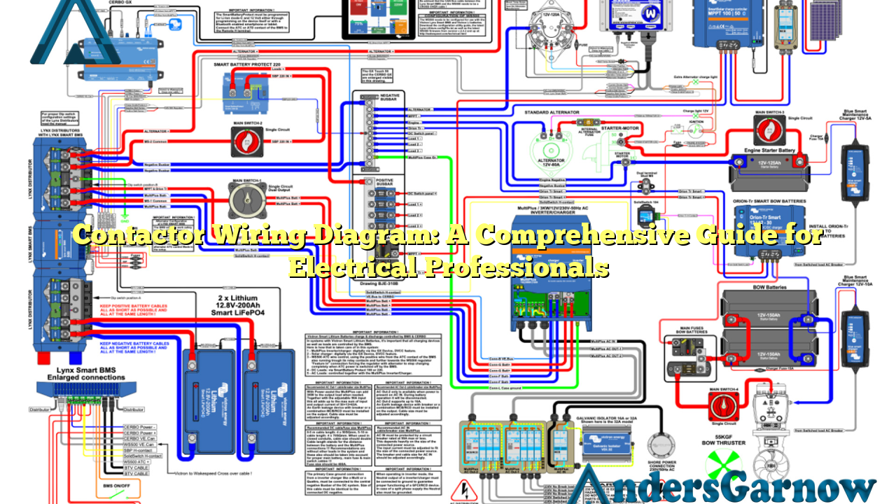
A contactor wiring diagram is a visual representation of the electrical connections and components involved in a contactor circuit. It illustrates the arrangement of contact points, control circuits, power supply, and load connections. By referring to a contactor wiring diagram, electricians can easily understand how to wire and connect different elements of a contactor circuit.
Contactor wiring diagrams are commonly used in industrial and commercial applications where a high voltage or current needs to be controlled. These diagrams ensure proper wiring, prevent short circuits, and enable easy troubleshooting.
2. Benefits of Contactor Wiring Diagrams
Contactors are essential components in electrical systems, and using wiring diagrams offers several advantages:
- Clarity: Contactors wiring diagrams provide a clear and concise representation of complex electrical connections, making it easier to understand and follow.
- Efficiency: By following a contactor wiring diagram, electricians can complete installations or repairs more efficiently, saving time and effort.
- Safety: Wiring diagrams ensure that contactors are correctly wired, minimizing the risk of electrical accidents, short circuits, or equipment damage.
- Troubleshooting: When a contactor circuit malfunctions, a wiring diagram becomes invaluable for identifying and rectifying the issue.
3. Drawbacks of Contactor Wiring Diagrams
While contactor wiring diagrams offer significant benefits, they also have a few drawbacks:
- Complexity: Some contactor wiring diagrams can be complex, especially in large-scale electrical systems, which may require additional expertise to interpret and implement.
- Updates: Wiring diagrams may need to be updated frequently to reflect any changes or modifications made to the electrical system.
- Dependence on Accuracy: The accuracy of a contactor wiring diagram is crucial. Any errors or omissions can lead to improper connections and potential safety hazards.
4. Exploring Alternatives
While contactor wiring diagrams are widely used, there are alternative options available for specific applications:
- Motor Control Centers (MCCs): In large industrial setups, MCCs provide a centralized control panel for multiple motors, reducing the complexity of wiring individual contactors.
- Programmable Logic Controllers (PLCs): PLCs offer advanced control capabilities and programmability, replacing the need for contactors in some applications.
- Solid-State Relays (SSRs): SSRs provide an electronic alternative to traditional electromechanical contactors, offering faster switching speeds and longer lifespan.
5. Contactor Wiring Diagram: Detailed Breakdown
Now, let’s dive into the detailed breakdown of a typical contactor wiring diagram:
| Component | Description |
|---|---|
| Contact Points | These are the physical contacts that allow or interrupt the flow of electricity in the circuit. |
| Coil | The coil is an electromagnetic component that controls the opening and closing of the contact points. |
| Control Circuit | This circuit includes switches, relays, and other control devices that activate the coil to control the contactor. |
| Power Supply | The power supply provides the necessary voltage and current to energize the coil and operate the contactor. |
| Load Connections | These connections enable the contactor to control the power supply to the load, such as motors, lights, or heaters. |
6. Frequently Asked Questions (FAQ)
Here are some frequently asked questions regarding contactor wiring diagrams:
Q: Can I use any contactor wiring diagram for my project?
A: It is recommended to use a contactor wiring diagram that matches your specific contactor model and the electrical requirements of your project. Using an incorrect diagram may result in improper connections or circuit malfunctions.
Q: Are contactor wiring diagrams universal?
A: While the basic principles of contactor wiring diagrams remain the same, there can be variations based on the manufacturer, contactor model, and specific application. Always refer to the manufacturer’s documentation for accurate diagrams relevant to your contactor.
Q: Can I modify a contactor wiring diagram?
A: Modifying a contactor wiring diagram without proper knowledge and expertise can lead to safety hazards or equipment damage. It is recommended to consult with a qualified electrician or follow the manufacturer’s instructions for any modifications.
Conclusion
In conclusion, contactor wiring diagrams are essential tools for electrical professionals and enthusiasts alike. They provide a visual representation of complex contactor circuits, ensuring proper connections, safety, and efficient troubleshooting. While they may have some drawbacks, alternative options such as MCCs, PLCs, and SSRs offer flexibility for specific applications. By understanding the detailed breakdown of contactor wiring diagrams and following best practices, you can effectively implement these diagrams to enhance the reliability and performance of your electrical systems.
