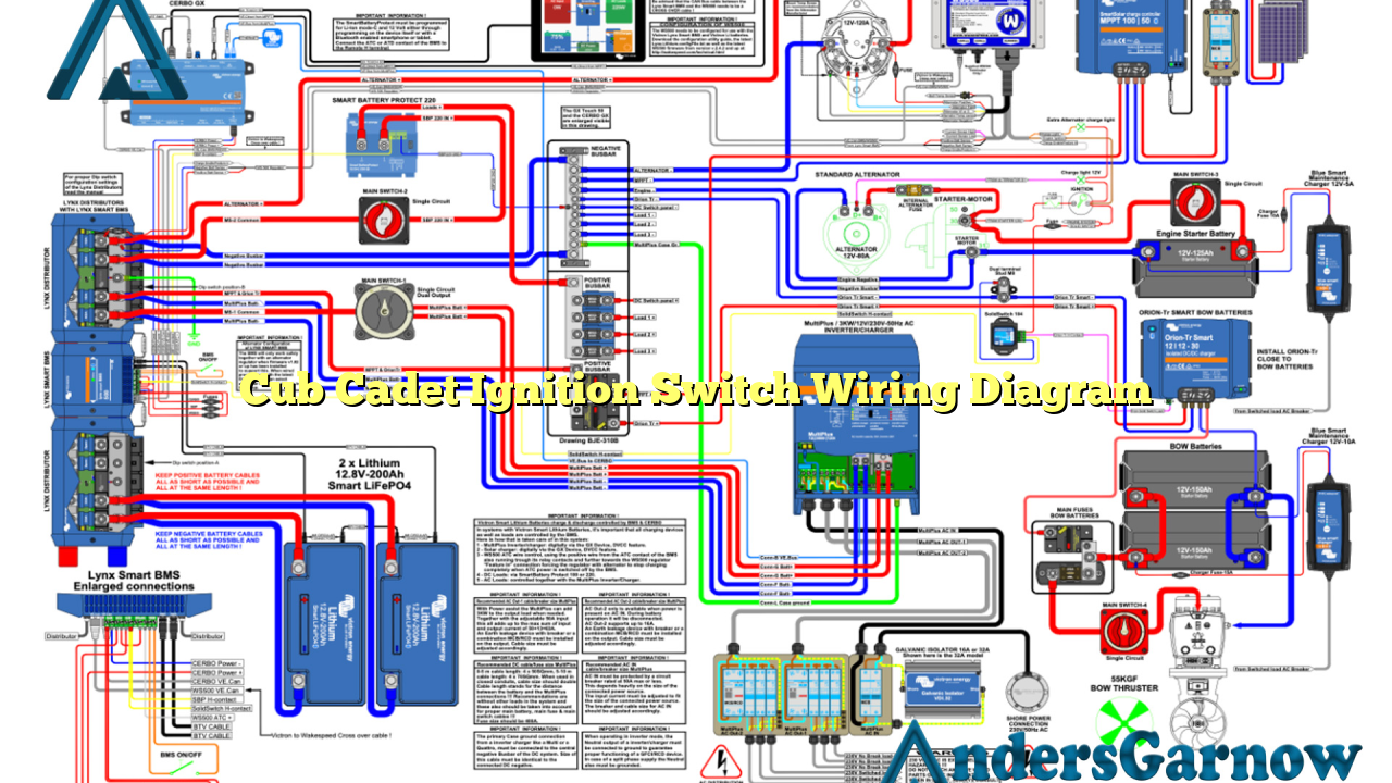
Hello readers! In this article, we will discuss the Cub Cadet ignition switch wiring diagram in detail. This diagram is essential for understanding the electrical connections and functionality of the ignition switch in Cub Cadet equipment. Whether you are a DIY enthusiast or a professional mechanic, this information will guide you through the process of wiring the ignition switch correctly.
1. Understanding the Ignition Switch
The ignition switch is a crucial component in any Cub Cadet equipment. It is responsible for controlling the flow of electrical power from the battery to the starter motor, allowing the engine to start. Understanding the different terminals and connections on the ignition switch is essential for proper wiring.
2. Wiring Diagram Overview
The Cub Cadet ignition switch wiring diagram consists of various components, including the battery, starter solenoid, ignition module, ignition coil, and the ignition switch itself. The diagram illustrates the connections between these components and their respective terminals on the ignition switch.
3. Terminal Identification
Each terminal on the ignition switch is labeled with a specific letter or number for identification. Understanding these terminal labels is crucial for accurate wiring. The most common terminal designations on a Cub Cadet ignition switch are B, M, S, and G, which stand for Battery, Magneto, Starter Solenoid, and Ground, respectively.
4. Wiring the Battery Terminal
The battery terminal on the ignition switch is responsible for connecting the positive terminal of the battery to the switch. This connection ensures a constant supply of electrical power to the switch and other components. It is important to follow the wiring diagram carefully to avoid any electrical issues.
5. Wiring the Magneto Terminal
The magneto terminal on the ignition switch is connected to the ignition coil, which generates the high-voltage spark required to ignite the fuel-air mixture in the engine. Proper wiring of this terminal is essential for a reliable ignition system.
6. Wiring the Starter Solenoid Terminal
The starter solenoid terminal on the ignition switch is responsible for activating the starter motor. When the switch is turned to the “start” position, it sends a signal to the starter solenoid, which then engages the starter motor to crank the engine. Accurate wiring of this terminal is crucial for smooth engine starting.
7. Wiring the Ground Terminal
The ground terminal on the ignition switch is connected to the frame of the Cub Cadet equipment. It provides a path for electrical current to return to the battery’s negative terminal, completing the circuit. Proper grounding is essential for the overall electrical system’s functionality.
8. The Importance of Proper Wiring
Proper wiring of the ignition switch is crucial for the safety and functionality of the Cub Cadet equipment. Incorrect wiring can lead to electrical shorts, malfunctions, and even fire hazards. Always refer to the wiring diagram and follow the manufacturer’s guidelines for accurate wiring.
9. Alternatives to the Cub Cadet Ignition Switch Wiring Diagram
While the Cub Cadet ignition switch wiring diagram is the recommended reference for wiring the ignition switch, there are alternative sources of information available. Online forums, Cub Cadet service manuals, and professional mechanics can provide additional guidance and insights into wiring the ignition switch.
10. Cub Cadet Ignition Switch Wiring Diagram Table
| Terminal | Description |
|---|---|
| B | Battery Terminal |
| M | Magneto Terminal |
| S | Starter Solenoid Terminal |
| G | Ground Terminal |
Conclusion
In conclusion, understanding the Cub Cadet ignition switch wiring diagram is essential for accurate wiring and optimal performance of your Cub Cadet equipment. By following the wiring diagram and paying attention to the terminal connections, you can ensure a reliable and safe ignition system. Remember, always consult the manufacturer’s guidelines and seek professional assistance if needed. Happy wiring!

