Hello and welcome to our comprehensive guide on electric schematic! In this article, we will delve into the world of electrical schematics, exploring their purpose, components, advantages, and limitations. Whether you are an aspiring electrician, an engineering enthusiast, or simply curious about the inner workings of electrical systems, this article will provide you with valuable insights. So, let’s get started!
1. What is an Electric Schematic?
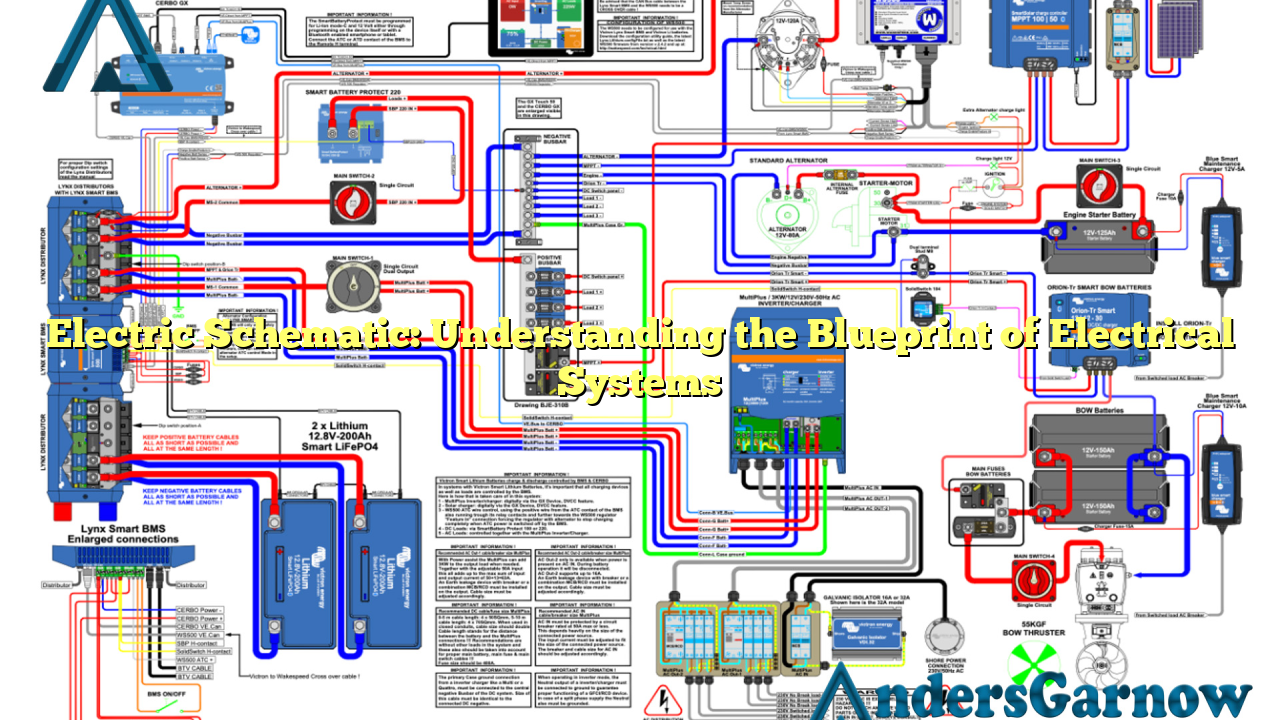
An electric schematic, also known as an electrical diagram or wiring diagram, is a graphical representation of an electrical circuit. It uses standardized symbols to depict the components and connections within the circuit. Electric schematics serve as a blueprint for understanding and troubleshooting electrical systems, ranging from simple circuits to complex industrial installations.
2. Components of an Electric Schematic
An electric schematic consists of various components, each represented by unique symbols. Some common components include resistors, capacitors, inductors, switches, transformers, and power sources. These symbols allow engineers and technicians to identify and understand the functionality of each component within the circuit.
3. Advantages of Electric Schematic
Electric schematics offer several key advantages, including:
- Clarity: Schematics provide a clear and concise representation of complex electrical systems, making it easier to understand the circuit’s functionality.
- Troubleshooting: When electrical systems malfunction, schematics serve as a valuable tool for identifying faulty components and troubleshooting the circuit.
- Standardization: Electric schematics follow standardized symbols and conventions, allowing engineers and technicians worldwide to communicate and understand circuit designs effectively.
- Documentation: Schematics serve as a documented record of electrical systems, aiding in maintenance, repairs, and future modifications.
4. Limitations of Electric Schematic
While electric schematics are highly useful, they do have some limitations:
- Abstraction: Schematics represent electrical systems in an abstract manner, focusing on the circuit’s functionality rather than physical layout, which may make it challenging to visualize the actual arrangement.
- Complexity: In complex electrical systems, schematics can become intricate and overwhelming, requiring advanced knowledge and experience to interpret accurately.
- Updates: As electrical systems evolve, schematics may become outdated, necessitating regular updates to reflect any modifications or additions.
5. Alternative Approaches to Electric Schematic
While electric schematics are widely used, there are alternative approaches to represent electrical systems:
- Block Diagrams: Block diagrams focus on the functional blocks within an electrical system, simplifying the representation by omitting detailed component connections.
- PCB Layouts: Printed Circuit Board (PCB) layouts provide a physical representation of the circuit, showcasing the exact placement of components and their interconnections.
- 3D Models: In modern engineering, 3D models and simulations are often used to visualize and analyze complex electrical systems, offering a more intuitive representation.
6. Electric Schematic: A Detailed Analysis
To further understand electric schematics, let’s delve into a detailed analysis of its key aspects:
| Aspect | Description |
|---|---|
| Symbols | Electric schematics utilize standardized symbols to represent various components, ensuring uniformity and easy identification. |
| Lines | Lines in schematics depict the connections between components, indicating the flow of current and signal pathways. |
| Labels | Labels are used to provide additional information such as component values, ratings, or specific details relevant to the circuit. |
| Arrows | Arrows indicate the direction of current flow within the circuit, helping to understand the circuit’s functionality. |
| Ground Symbol | The ground symbol represents the reference point for voltage measurements and is crucial for understanding the circuit’s electrical potential. |
7. Frequently Asked Questions (FAQ)
1. Why are electric schematics important?
Electric schematics are essential for understanding, troubleshooting, and designing electrical systems. They provide a visual representation of circuits, making it easier to comprehend their functionality and identify potential issues.
2. How can I learn to read electric schematics?
Learning to read electric schematics requires familiarity with electrical symbols, understanding circuit connections, and knowledge of electrical principles. Online tutorials, textbooks, and practical experience can help in developing this skill.
3. Are there software tools available for creating electric schematics?
Yes, there are various software tools available such as AutoCAD Electrical, Eagle, and KiCad that facilitate the creation and editing of electric schematics. These tools provide a user-friendly interface and a vast library of pre-defined symbols for efficient diagramming.
4. Can electric schematics be used for all types of electrical systems?
Electric schematics can be used for a wide range of electrical systems, from simple residential circuits to complex industrial installations. However, for extremely intricate systems, additional documentation such as interconnection drawings and panel layouts may be necessary.
5. How often should electric schematics be updated?
Electric schematics should be updated whenever modifications or additions are made to an electrical system. Regular reviewing and updating of schematics ensure that they accurately represent the current state of the circuit and aid in future maintenance and troubleshooting.
8. Conclusion
In conclusion, electric schematics are invaluable tools for understanding, troubleshooting, and designing electrical systems. They provide a standardized and visual representation of circuits, enabling engineers and technicians to comprehend the intricate workings of electrical systems. While they have certain limitations, such as abstraction and complexity, their advantages outweigh these drawbacks. By understanding electric schematics, one can unlock the blueprint of electrical systems and gain insights into the fascinating world of electricity.
