Hello! If you have ever wondered how electrical devices work or how to troubleshoot electrical problems, understanding electrical circuit diagrams is essential. In this article, we will delve into the world of electrical circuit diagrams, exploring their purpose, components, advantages, and disadvantages. So, let’s get started!
1. What is an Electrical Circuit Diagram?
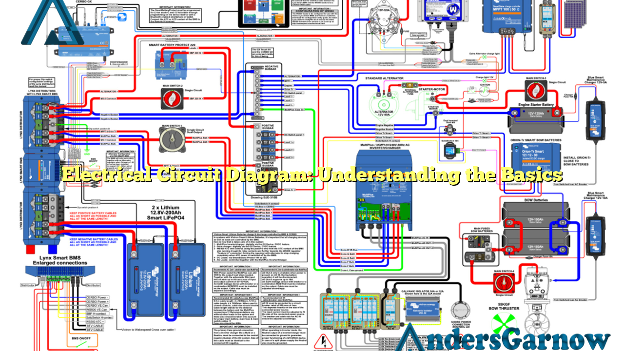
An electrical circuit diagram, also known as a schematic diagram, is a graphical representation of an electrical circuit. It uses symbols to illustrate the components and connections within the circuit, providing a blueprint for understanding and analyzing the circuit’s behavior.
By using standardized symbols, electrical circuit diagrams facilitate clear communication between engineers, electricians, and technicians. They are widely used in various industries, including electronics, telecommunications, power systems, and automotive.
2. Components of an Electrical Circuit Diagram
An electrical circuit diagram consists of several key components:
| Component | Description |
|---|---|
| Symbols | Represent various electrical devices and components, such as resistors, capacitors, switches, and transformers. |
| Lines and Arrows | Indicate the connections between components and the flow of current within the circuit. |
| Labels | Provide additional information, such as component values, voltage levels, and signal names. |
These components work together to create a visual representation of the circuit, enabling users to understand its structure and functionality.
3. Advantages of Electrical Circuit Diagrams
Electrical circuit diagrams offer several advantages:
- Clarity: Circuit diagrams provide a clear and concise representation of complex electrical systems, making it easier to understand and analyze their functionality.
- Troubleshooting: When electrical problems occur, circuit diagrams serve as valuable troubleshooting tools, allowing technicians to identify and resolve issues more efficiently.
- Standardization: The use of standardized symbols and conventions in circuit diagrams ensures consistency and facilitates communication among professionals in the field.
4. Disadvantages of Electrical Circuit Diagrams
While electrical circuit diagrams offer numerous benefits, they also have some limitations:
- Complexity: Circuit diagrams can become complex, especially for large-scale electrical systems, making them challenging to interpret for individuals with limited knowledge or experience.
- Learning Curve: Understanding and creating circuit diagrams require a certain level of technical expertise, which may take time and effort to acquire.
- Updates: As electrical systems evolve and components change, circuit diagrams need to be updated regularly to reflect the latest configurations.
5. Alternative Approaches to Electrical Circuit Diagrams
While electrical circuit diagrams are the most common method for representing circuits, there are alternative approaches available:
- Breadboard Layouts: For prototyping and testing circuits, breadboard layouts provide a physical representation, allowing users to connect components without soldering.
- Block Diagrams: Block diagrams focus on the overall functionality of a system, rather than its detailed electrical connections. They are often used in systems engineering and control systems.
- Flowcharts: In some cases, flowcharts can be used to represent the logical flow of a circuit, emphasizing decision-making and control processes.
Conclusion
In conclusion, electrical circuit diagrams are valuable tools for understanding, analyzing, and troubleshooting electrical circuits. They provide a visual representation of the circuit’s components and connections, promoting clarity and standardization in the field of electrical engineering. While they have some limitations, their advantages far outweigh the disadvantages. So, whether you are an aspiring engineer or a curious individual, familiarizing yourself with electrical circuit diagrams will enhance your understanding of the fascinating world of electricity.
Frequently Asked Questions (FAQ)
Q: Are there software tools available for creating electrical circuit diagrams?
A: Yes, several software tools, such as AutoCAD Electrical, EAGLE, and Multisim, provide features specifically designed for creating and editing electrical circuit diagrams.
Q: Can I use circuit diagrams to repair household electrical appliances?
A: It is generally not recommended for individuals without proper training to attempt repairing household electrical appliances based solely on circuit diagrams. Always prioritize safety and consider seeking professional assistance.
Q: How can I improve my understanding of electrical circuit diagrams?
A: You can start by studying basic electrical circuit theory and familiarizing yourself with common electrical symbols. Additionally, practicing drawing and interpreting circuit diagrams will further enhance your understanding.
