Hello, dear readers! In this article, we will delve into the intricacies of electrical diagrams, their importance, advantages, disadvantages, and alternative options. Electrical diagrams play a crucial role in various industries, from manufacturing and construction to automotive and electronics. So, let’s begin our journey to unravel the mysteries of electrical diagrams!
1. Understanding Electrical Diagrams
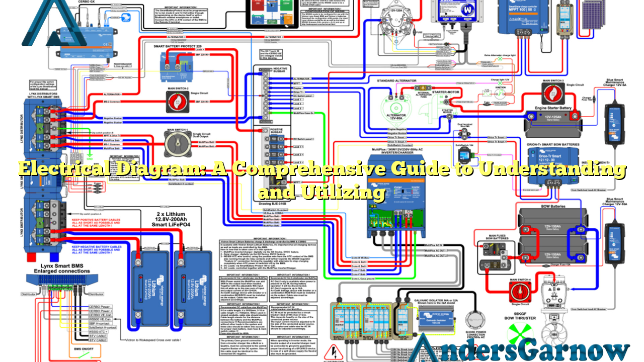
Electrical diagrams, also known as wiring diagrams or circuit diagrams, are visual representations of electrical circuits. These diagrams use symbols to depict the electrical components and their interconnections, providing a clear and concise overview of the circuit’s structure and functionality.
Advantages of Electrical Diagrams:
| Advantages | Explanation |
|---|---|
| Clear Communication | Electrical diagrams enable efficient communication and understanding among engineers, electricians, and technicians. They can easily interpret the diagram to identify issues or make modifications. |
| Fault Diagnosis | Electrical diagrams aid in troubleshooting electrical faults. By examining the diagram, professionals can pinpoint the problematic area and rectify the issue promptly. |
| Enhanced Safety | Using electrical diagrams ensures that circuits are correctly wired, reducing the risk of electrical accidents, short circuits, and fires. |
| Efficient Planning | Electrical diagrams facilitate efficient planning and installation of electrical systems. They provide a blueprint for engineers and electricians to follow during construction or maintenance projects. |
Disadvantages of Electrical Diagrams:
While electrical diagrams offer numerous advantages, they also have some limitations. Here are a few disadvantages:
- Complexity: Electrical diagrams can be complex, especially for intricate circuits. Understanding the symbols and connections requires expertise and experience.
- Updates: As electrical systems evolve or undergo modifications, diagrams may become outdated. Regular updates are necessary to ensure accuracy.
- Interpretation Errors: Misinterpreting symbols or connections can lead to circuit malfunctions or accidents. Attention to detail is vital.
2. Alternative Options: Computer-Aided Design (CAD)
Computer-Aided Design (CAD) software provides an alternative to traditional electrical diagrams. CAD tools offer advanced features and automation, simplifying the design and documentation process. They allow engineers to create, modify, and simulate electrical circuits digitally. CAD software also facilitates collaborative work, making it easier to share designs and modifications with team members.
FAQs (Frequently Asked Questions) about Electrical Diagrams:
Q: Can I create electrical diagrams manually without software?
A: Yes, you can create electrical diagrams manually using pen and paper or specialized drafting tools. However, software tools like CAD provide more convenience and flexibility.
Q: How do I learn to interpret electrical diagrams?
A: Interpreting electrical diagrams requires knowledge of electrical symbols and circuitry. You can learn through educational courses, online tutorials, or by referring to industry-standard books and resources.
Q: Are electrical diagrams only relevant to professionals?
A: While professionals primarily use electrical diagrams, they can also be valuable for DIY enthusiasts. Understanding electrical diagrams can aid in home wiring projects or troubleshooting simple electrical issues.
Conclusion:
In conclusion, electrical diagrams are indispensable tools for engineers, electricians, and technicians. They provide a visual representation of electrical circuits and aid in communication, troubleshooting, safety, and efficient planning. While they have some limitations, alternative options like CAD software offer advanced features. By mastering the interpretation of electrical diagrams, professionals and enthusiasts alike can ensure the smooth functioning of electrical systems.
