Hello, dear readers! In this article, we will delve into the world of electrical schematics, providing you with a detailed understanding of what they are, their advantages and disadvantages, and alternative options. So, let’s get started!
1. What is an Electrical Schematic?
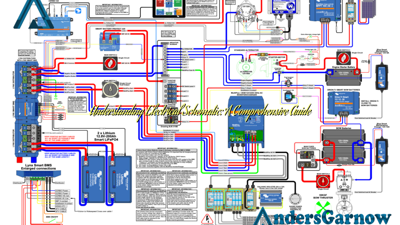
An electrical schematic, also known as a circuit diagram or wiring diagram, is a visual representation of an electrical circuit. It uses symbols to illustrate the components and interconnections of the circuit, allowing technicians and engineers to understand and troubleshoot electrical systems.
2. The Advantages of Electrical Schematics
Electrical schematics offer several benefits, including:
- Clear Visualization: Schematics provide a clear and concise visual representation of the circuit, making it easier to understand and interpret.
- Troubleshooting Aid: When electrical systems malfunction, schematics help technicians identify the faulty components and their connections, facilitating faster repairs.
- Standardization: Schematics follow standardized symbols and conventions, enabling effective communication among professionals across different industries.
- Documentation: Schematics serve as valuable documentation for future reference, maintenance, and modifications.
3. The Limitations of Electrical Schematics
While electrical schematics are widely used, they do have some limitations:
- Complexity: Schematics can become complex, especially for intricate circuits, leading to potential confusion and errors.
- No Physical Representation: Schematics do not provide a physical depiction of the circuit, making it challenging to visualize the actual layout and size of components.
- No Real-Time Data: Schematics do not convey real-time data, such as voltage fluctuations or current variations, which may be crucial for certain applications.
4. Alternatives to Electrical Schematics
While electrical schematics are widely used, there are alternative methods to represent circuits:
- Block Diagrams: Block diagrams focus on the functional relationship between components rather than the actual connections, providing a broader overview of the system.
- Breadboard Layouts: Breadboard layouts involve physically connecting components on a breadboard, allowing for quick prototyping and experimentation.
- PCB Layouts: PCB layouts depict the physical arrangement of components on a printed circuit board, providing a detailed representation of the final product.
5. Comprehensive Information about Electrical Schematic
To provide you with a comprehensive understanding of electrical schematics, we have compiled the following table:
| Aspect | Description |
|---|---|
| Symbols | Electrical schematics utilize standardized symbols to represent various components, such as resistors, capacitors, and transistors. |
| Connections | Schematics illustrate the connections between components, including the direction of current flow and the type of connection (series or parallel). |
| Power Source | The power source, such as a battery or power supply, is indicated in the schematic, along with its voltage and polarity. |
| Grounding | Ground symbols are used to represent the reference point for voltage measurements and the connection to the Earth. |
| Labels | Schematics include labels to identify components, nodes, and connections, ensuring clarity and ease of understanding. |
6. Frequently Asked Questions (FAQ) about Electrical Schematic
Q: Are electrical schematics only used by professionals?
A: While professionals extensively use electrical schematics, hobbyists and enthusiasts can also benefit from understanding and creating schematics for their projects.
Q: Can I create my own electrical schematic?
A: Yes, several software tools and online platforms allow users to create their own electrical schematics, even without extensive technical knowledge.
Q: Are electrical schematics universal?
A: While the symbols and conventions for electrical schematics are generally standardized, there may be slight variations in specific industries or regions.
Conclusion
In conclusion, electrical schematics are invaluable tools for understanding, troubleshooting, and documenting electrical circuits. They offer clear visualization, aid in troubleshooting, and foster communication among professionals. However, they can become complex and lack physical representation. Alternatives like block diagrams, breadboard layouts, and PCB layouts provide different perspectives on circuit representation. Understanding the symbols, connections, and other aspects of electrical schematics equips you with the knowledge to comprehend and work with electrical circuits effectively.
