Hello readers! In this article, we will delve into the world of electrical schematic diagrams. A crucial tool used by electrical engineers, these diagrams provide a visual representation of an electrical circuit. They are essential for designing, troubleshooting, and understanding complex electrical systems.
1. What is an Electrical Schematic Diagram?
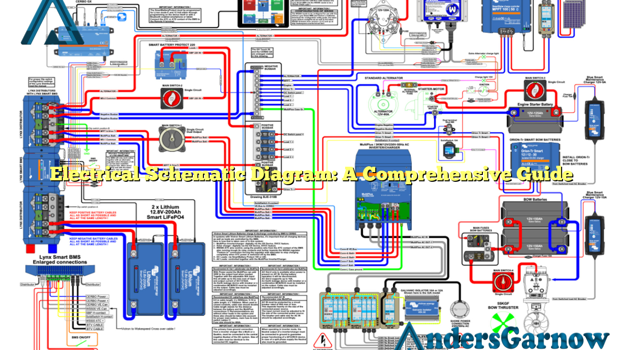
An electrical schematic diagram, also known as a circuit diagram or wiring diagram, is a graphical representation of an electrical circuit. It uses standardized symbols to depict the components and interconnections of the circuit. This visual representation helps engineers understand the overall structure and functioning of the system.
Advantages:
- Clear visualization: Schematic diagrams provide a clear and concise visual representation of complex electrical systems, making it easier to understand and analyze.
- Troubleshooting aid: These diagrams assist in identifying and locating faults or issues within the circuit, enabling efficient troubleshooting.
- Design reference: Electrical engineers use schematic diagrams as a reference during the design and development of new electrical systems.
Disadvantages:
- Complexity: Schematic diagrams can become intricate and difficult to comprehend for larger and more complex electrical systems.
- Learning curve: Interpreting schematic diagrams requires a certain level of knowledge and expertise in electrical engineering.
- Space limitations: Creating a schematic diagram for an extensive electrical system might require a large amount of space.
2. Components of an Electrical Schematic Diagram
An electrical schematic diagram consists of various components, each represented by a specific symbol. Some common components found in these diagrams include:
| Component | Symbol | Description |
|---|---|---|
| Resistor |  Source: None Source: None |
A passive two-terminal electrical component that resists the flow of current. |
| Capacitor |  Source: None Source: None |
A device used to store and release electrical energy. |
| Inductor |  Source: None Source: None |
A passive two-terminal electrical component that stores energy in a magnetic field. |
| Transformer |  Source: None Source: None |
A device that transfers electrical energy between two or more circuits through electromagnetic induction. |
| Switch |  Source: None Source: None |
A device used to interrupt or divert the flow of electrical current in a circuit. |
3. Importance of Electrical Schematic Diagrams
Electrical schematic diagrams play a crucial role in various aspects of electrical engineering. Here are some reasons why they are important:
- Design and Development: Schematic diagrams serve as a blueprint for designing and developing electrical systems.
- Installation and Maintenance: These diagrams aid in the proper installation and maintenance of electrical systems, ensuring safety and efficiency.
- Documentation: Schematic diagrams provide a documented record of the electrical system, facilitating future modifications or repairs.
4. Alternatives to Electrical Schematic Diagrams
While electrical schematic diagrams are widely used and highly effective, there are alternative methods for representing electrical circuits. Some of these alternatives include:
- Block Diagrams: These diagrams use blocks to represent different components or subsystems of the electrical circuit, providing a high-level overview of the system.
- Breadboard Diagrams: Breadboard diagrams are commonly used in prototyping and experimentation. They allow engineers to physically connect components on a breadboard to test circuit designs.
- PCB Layouts: Printed Circuit Board (PCB) layouts provide a detailed representation of the physical arrangement of components on a circuit board.
Frequently Asked Questions (FAQ)
Q: Can I create an electrical schematic diagram without any specialized software?
A: Yes, it is possible to create a basic electrical schematic diagram using standard drawing software such as Microsoft Visio or even with pen and paper. However, specialized software offers more advanced features and a wider range of symbols for complex diagrams.
Q: How can I learn to read and interpret electrical schematic diagrams?
A: Learning to read and interpret electrical schematic diagrams requires a combination of theoretical knowledge and practical experience. There are numerous online resources, textbooks, and courses available that can help you acquire the necessary skills.
Q: Are there any industry standards for electrical schematic diagrams?
A: Yes, several industry standards provide guidelines for creating electrical schematic diagrams, such as the International Electrotechnical Commission’s IEC 60617 standard and the National Electrical Manufacturers Association’s NEMA standards.
In Conclusion
In conclusion, electrical schematic diagrams are invaluable tools for electrical engineers, enabling them to design, troubleshoot, and understand complex electrical systems. While they have some limitations, their advantages outweigh the disadvantages. By using standardized symbols and clear visual representations, these diagrams provide a comprehensive understanding of electrical circuits.
