Hello readers! In this article, we will delve into the fascinating world of electrical schematics. As the backbone of any electrical system, schematics provide a detailed visual representation of the circuitry and components involved. Whether you are an aspiring electrician or simply curious about how things work, this comprehensive guide will equip you with the knowledge to navigate through the complexities of electrical schematics.
1. What are Electrical Schematics?
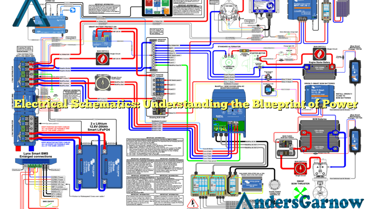
Electrical schematics, also known as wiring diagrams, are graphical representations of an electrical circuit. They illustrate how various components, such as switches, resistors, capacitors, and more, are interconnected to form a functional system. Schematics use standardized symbols and lines to depict the flow of electricity, making it easier to understand and troubleshoot electrical systems.
Advantages of Electrical Schematics:
| Advantages | Disadvantages |
|---|---|
| Simplified representation of complex systems | Requires technical knowledge to interpret |
| Efficient troubleshooting and diagnostics | May be time-consuming to create |
| Standardized symbols for universal understanding | Can be overwhelming for beginners |
| Facilitates accurate circuit design and modifications | May not capture all nuanced details |
Despite some drawbacks, the advantages of electrical schematics outweigh the challenges, making them an invaluable tool in the world of electrical engineering.
2. Components of an Electrical Schematic
An electrical schematic consists of several key elements:
- Symbols: Each component is represented by a unique symbol, allowing for quick identification.
- Lines: These indicate the connections between components, illustrating the flow of electricity.
- Labels: Descriptive text is used to provide additional information about specific components or connections.
- Notes: These annotations offer further clarification or instructions for understanding the schematic.
By understanding the different components of an electrical schematic, one can decipher the intricate relationships between various elements within a circuit.
3. Types of Electrical Schematics
There are several types of electrical schematics, each serving a specific purpose:
- Wiring Diagrams: These depict the physical layout and connections between components in a system.
- Block Diagrams: These provide a high-level overview of a system, focusing on major functional blocks.
- Circuit Diagrams: These show the detailed circuitry of a specific component or subsystem within a larger system.
- Pictorial Diagrams: These use realistic images of components instead of standardized symbols, making them more accessible to beginners.
Each type of schematic has its own advantages and applications, catering to different needs and levels of complexity.
4. Importance of Electrical Schematics
Electrical schematics play a vital role in various fields, including:
- Electrical Engineering: Schematics enable engineers to design, analyze, and modify electrical systems efficiently.
- Electricians: These diagrams aid electricians in troubleshooting faults, installing new equipment, and maintaining existing systems.
- Manufacturing: Schematics are crucial for producing and assembling electrical components in a standardized and efficient manner.
By providing a visual roadmap of electrical systems, schematics ensure safety, accuracy, and reliability in a wide range of applications.
5. Common Challenges in Reading Schematics
While electrical schematics are invaluable tools, they can pose challenges, especially for beginners. Some common hurdles include:
- Complexity: Elaborate circuits with numerous components may overwhelm those with limited experience.
- Technical Jargon: Understanding the symbols and terminology used in schematics requires familiarity with electrical concepts.
- Missing Information: Schematics may not always capture every detail, requiring additional knowledge or reference materials.
Overcoming these challenges requires patience, practice, and a solid foundation in electrical principles.
6. Alternatives to Electrical Schematics
While electrical schematics are the standard in the industry, alternative methods also exist:
- Textual Descriptions: Detailed written instructions can provide step-by-step guidance for electrical systems.
- Flowcharts: These visual representations use symbols and arrows to illustrate the sequence of operations in a system.
- Physical Prototypes: Building physical models allows for hands-on understanding of how electrical systems work.
While these alternatives may be useful in certain scenarios, they lack the comprehensive nature and precision of electrical schematics.
7. Frequently Asked Questions (FAQ)
Q: Are electrical schematics the same as circuit diagrams?
A: Circuit diagrams are a type of electrical schematic that focuses on the detailed circuitry of a specific component or subsystem.
Q: How can I learn to read electrical schematics?
A: Familiarize yourself with electrical symbols, study circuit diagrams, and practice interpreting schematics with the help of guides and tutorials.
Q: Can I modify an electrical schematic?
A: Yes, electrical schematics are meant to be modified and customized according to specific project requirements or system upgrades.
In Conclusion
Electrical schematics are the backbone of modern electrical systems, providing a visual representation of complex circuits and components. Despite their technical nature, schematics offer a standardized and efficient way to design, troubleshoot, and understand electrical systems. By mastering the art of reading schematics, one can unlock a world of possibilities in the field of electrical engineering.
