Hello readers, welcome to this comprehensive article about electronic diagrams. In the world of electronics, an electronic diagram serves as a blueprint, providing a visual representation of the components, connections, and functions of electronic circuits. In this article, we will delve into the intricacies of electronic diagrams, exploring their benefits, drawbacks, and alternative options.
1. The Importance of Electronic Diagrams
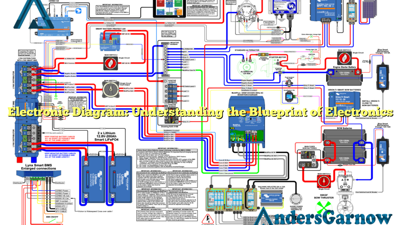
Electronic diagrams play a pivotal role in the design, analysis, and troubleshooting of electronic circuits. They serve as a visual guide for engineers, technicians, and hobbyists, ensuring accurate assembly and functionality of electronic devices.
Advantages:
- Clear Visualization: Electronic diagrams provide a clear and concise visual representation of complex circuits, making it easier to understand the connections and components.
- Troubleshooting Aid: When a circuit malfunctions, electronic diagrams act as a valuable tool for identifying faulty components or incorrect connections, streamlining the troubleshooting process.
- Design Optimization: By using electronic diagrams, engineers can optimize circuit designs by analyzing the flow of current, voltage drops, and potential areas of improvement.
Disadvantages:
- Complexity: Electronic diagrams can be complex, especially for intricate circuits, which may pose challenges for beginners or individuals with limited technical knowledge.
- Space Constraints: Representing a large circuit in a single diagram can lead to space constraints and make it difficult to comprehend the entire circuit at a glance.
- Version Control: With design iterations and modifications, keeping track of various versions of electronic diagrams can become cumbersome.
2. Alternative Options to Electronic Diagrams
While electronic diagrams are widely used, there are alternative options available for representing circuits:
Schematic Diagrams:
Schematic diagrams are similar to electronic diagrams, but they focus more on the logical flow of a circuit. They provide a high-level overview of the circuit’s functionality without delving into intricate details.
Breadboard Layouts:
Breadboard layouts involve physically assembling electronic components on a breadboard to represent the circuit. This hands-on approach allows for easy experimentation and prototyping.
Simulation Software:
Simulation software, such as SPICE (Simulation Program with Integrated Circuit Emphasis), enables engineers to create virtual circuit diagrams and simulate their behavior. This allows for testing and analysis without the need for physical components.
3. Complete Information about Electronic Diagrams
| Aspect | Details |
|---|---|
| Purpose | Visual representation of electronic circuits |
| Components | Resistors, capacitors, transistors, diodes, integrated circuits, etc. |
| Connections | Lines representing electrical connections between components |
| Types | Schematic diagrams, wiring diagrams, block diagrams, etc. |
| Software | AutoCAD, EAGLE, KiCad, etc. |
| Importance | Design, analysis, troubleshooting, and replication of circuits |
4. Frequently Asked Questions about Electronic Diagrams
Q: Can electronic diagrams be hand-drawn?
A: Yes, electronic diagrams can be hand-drawn, but using specialized software ensures accuracy, scalability, and ease of modification.
Q: Are electronic diagrams standardized?
A: Yes, there are standardized symbols and conventions for electronic diagrams, ensuring universal understanding among engineers and technicians.
Q: Can I create electronic diagrams for both analog and digital circuits?
A: Absolutely, electronic diagrams can represent both analog and digital circuits, allowing for comprehensive circuit analysis and design.
Conclusion
In conclusion, electronic diagrams are indispensable tools in the world of electronics. While they have their advantages, such as clear visualization and troubleshooting aid, they also come with drawbacks such as complexity and space constraints. However, alternative options like schematic diagrams, breadboard layouts, and simulation software offer flexibility and ease of use. Understanding electronic diagrams and their alternatives empowers individuals to excel in circuit design, analysis, and troubleshooting.
