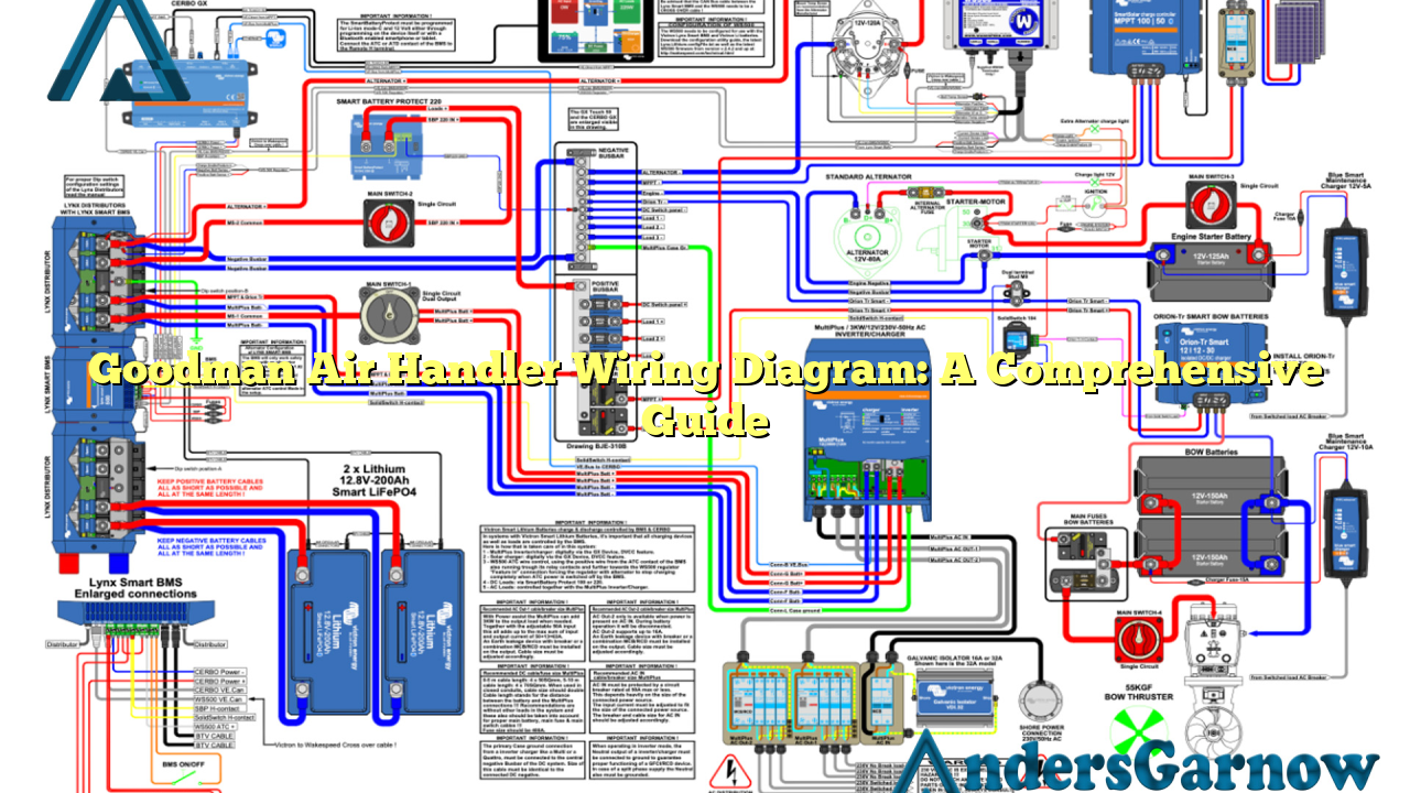
Hello readers! In this article, we will delve into the intricacies of Goodman air handler wiring diagrams. A crucial component of any HVAC system, air handlers play a significant role in ensuring optimal indoor air quality and comfortable temperatures. Understanding the wiring diagram is essential for proper installation and troubleshooting. Let’s explore this topic in detail.
1. Importance of a Goodman Air Handler Wiring Diagram
A wiring diagram serves as a roadmap for technicians to understand the electrical connections within an air handler. It provides a visual representation of the components and their interconnections, making it easier to identify and resolve issues. With a wiring diagram, professionals can ensure accurate installation, prevent electrical mishaps, and troubleshoot problems effectively.
2. Components of a Goodman Air Handler Wiring Diagram
A typical Goodman air handler wiring diagram consists of various components, including:
| Component | Description |
|---|---|
| Thermostat | Controls the heating and cooling system based on temperature settings. |
| Transformer | Converts the incoming voltage to the required voltage for the air handler. |
| Blower Motor | Circulates the conditioned air throughout the building. |
| Control Board | Regulates the operation of various components and communicates with the thermostat. |
| Capacitor | Stores electrical energy to provide an extra boost during startup. |
| Relays | Control the flow of electricity to different components. |
| Heat Strips | Provide supplementary heating during colder months. |
These components work together to ensure the proper functioning of the air handler.
3. Wiring Diagram Layout
A typical Goodman air handler wiring diagram consists of lines, symbols, and labels that represent the electrical connections between components. The layout may vary depending on the specific model and configuration. It is important to refer to the manufacturer’s documentation for the accurate wiring diagram corresponding to your air handler.
4. Understanding the Wiring Diagram
To comprehend the wiring diagram, it is crucial to understand the symbols used. Some common symbols found in Goodman air handler wiring diagrams include:
- Solid Lines: Represents electrical wires or conductors.
- Dashed Lines: Indicates connections that are not physically connected but are related electrically.
- Numbers and Letters: Used for identification purposes.
- Squares or Circles: Symbolize components.
- Arrows: Illustrate the flow of electricity.
By deciphering these symbols and understanding the connections, professionals can effectively install and troubleshoot the air handler.
5. Advantages of Goodman Air Handler Wiring Diagrams
Goodman air handler wiring diagrams offer several advantages, including:
- Accurate Installation: Technicians can follow the wiring diagram to ensure all components are connected correctly, minimizing the risk of errors during installation.
- Efficient Troubleshooting: A wiring diagram makes it easier to identify and resolve issues, saving time and effort during troubleshooting.
- Enhanced Safety: Proper wiring as per the diagram reduces the chances of electrical accidents and ensures the safety of both technicians and occupants.
6. Limitations of Goodman Air Handler Wiring Diagrams
While Goodman air handler wiring diagrams are valuable resources, they do have limitations, such as:
- Model-Specific: Wiring diagrams are specific to particular air handler models, so it is essential to use the correct diagram for accurate installations and troubleshooting.
- Technical Knowledge: Interpreting wiring diagrams requires a certain level of technical expertise, which may be challenging for individuals without prior experience.
- Complexity: Some wiring diagrams can be intricate, especially for advanced air handler systems, making it more challenging to understand and work with.
7. Alternative Methods for Goodman Air Handler Wiring
While the wiring diagram is the standard method for air handler installation, alternative methods include:
- Professional Assistance: Hiring a licensed HVAC technician ensures proper installation and eliminates the need for personal interpretation of wiring diagrams.
- Manufacturer Support: Contacting the manufacturer’s support team can provide guidance and assistance during the installation process.
- Online Resources: Online forums, tutorials, and videos can offer additional insights and step-by-step instructions for wiring a Goodman air handler.
Conclusion
Goodman air handler wiring diagrams are invaluable tools for HVAC professionals. They provide a visual representation of electrical connections, guiding technicians during installation and troubleshooting. While they have some limitations, the advantages of using wiring diagrams outweigh the challenges. By following the correct wiring diagram and seeking professional assistance when necessary, you can ensure a safe and efficient air handler installation.
Frequently Asked Questions (FAQ)
Q: Can I install a Goodman air handler without referring to the wiring diagram?
A: It is highly recommended to refer to the wiring diagram during installation to ensure proper connections and avoid any electrical issues.
Q: Where can I find the correct wiring diagram for my Goodman air handler?
A: The wiring diagram can usually be found in the installation manual provided by the manufacturer. You can also contact the manufacturer’s support team for assistance.
Q: What should I do if I encounter difficulties while interpreting the wiring diagram?
A: If you find it challenging to understand the wiring diagram, it is best to seek professional assistance from a licensed HVAC technician who has experience working with Goodman air handlers.
Q: Are there any precautions I should take while working with the electrical connections of a Goodman air handler?
A: It is crucial to turn off the power supply before working on any electrical connections. If you are unsure or uncomfortable working with electricity, it is best to seek professional help.

