Hello readers! In this article, we will explore the intricacies of a heat pump wiring diagram. Understanding the wiring diagram is crucial for proper installation and maintenance of a heat pump system. So, let’s dive in and unravel the mysteries behind this essential component.
1. Introduction to Heat Pump Wiring Diagram
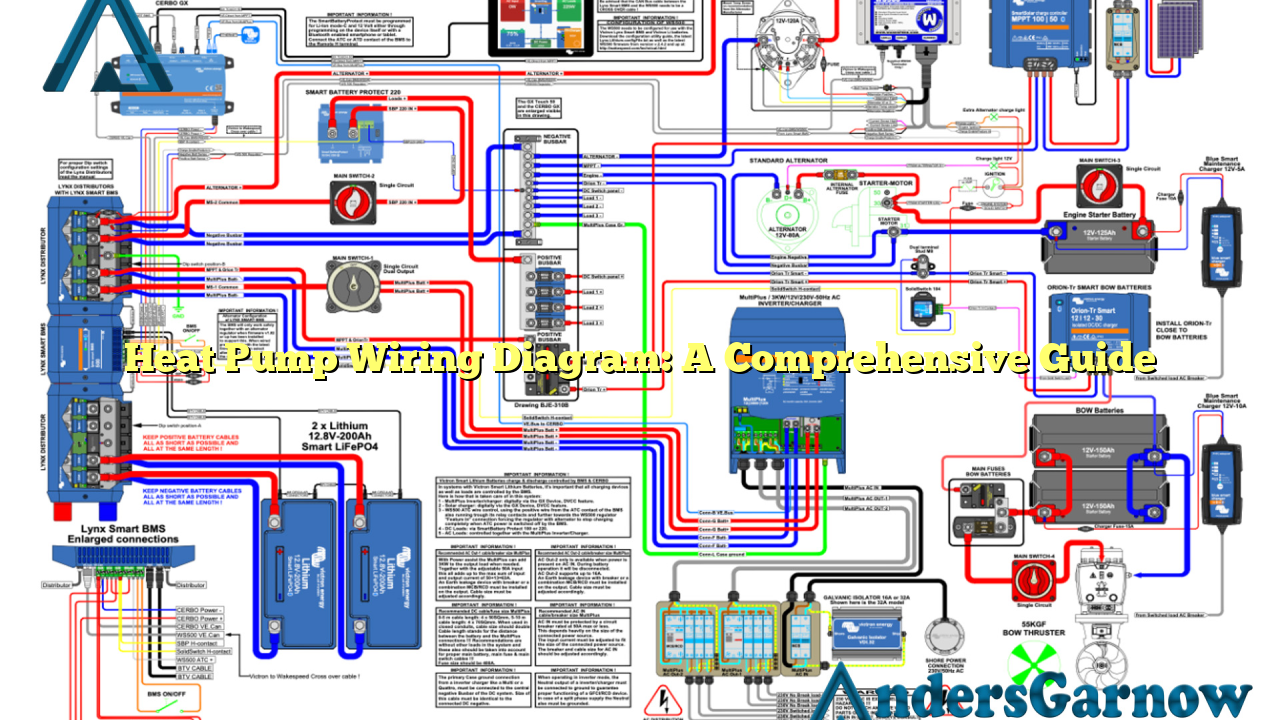
The heat pump wiring diagram is a visual representation of the electrical connections and components in a heat pump system. It outlines how various parts, such as the compressor, condenser, fan, and thermostat, are interconnected to ensure efficient operation of the heat pump.
Advantages:
– Provides a clear understanding of the electrical connections in the heat pump system.
– Facilitates troubleshooting and maintenance tasks.
Disadvantages:
– Requires technical knowledge and expertise to interpret the wiring diagram correctly.
– Inaccurate or outdated wiring diagrams can lead to improper installation or system malfunctions.
2. Understanding the Components
To comprehend the heat pump wiring diagram, let’s familiarize ourselves with the key components:
| Component | Description |
|---|---|
| Compressor | Main unit responsible for circulating refrigerant throughout the system. |
| Condenser | Converts high-pressure refrigerant vapor into a liquid state. |
| Fan | Blows air over the evaporator coil or the condenser coil to facilitate heat exchange. |
| Thermostat | Senses and regulates the temperature, activating or deactivating the heat pump as required. |
3. Wiring Diagram Configurations
The heat pump wiring diagram includes various configurations based on the specific model and manufacturer. Let’s explore some common configurations:
Single-Stage Heat Pump Wiring Diagram
In this configuration, the heat pump operates at a single heating or cooling capacity. It has a simple wiring setup that involves connecting the thermostat, compressor, condenser, and fan in a series or parallel circuit.
Dual-Stage Heat Pump Wiring Diagram
A dual-stage heat pump offers two levels of heating or cooling capacity, providing improved energy efficiency. The wiring diagram for a dual-stage heat pump includes additional components such as a dual-stage thermostat and a reversing valve.
Variable-Speed Heat Pump Wiring Diagram
Variable-speed heat pumps offer enhanced comfort and energy efficiency by adjusting the speed of the compressor and fan based on the desired temperature. The wiring diagram for a variable-speed heat pump involves more complex connections, including additional control modules.
4. Alternative Heat Pump Wiring Diagram
While the aforementioned configurations are common, it’s important to note that heat pump wiring diagrams can vary depending on the manufacturer and model. It is always recommended to refer to the specific wiring diagram provided by the manufacturer to ensure accurate installation and operation.
5. Frequently Asked Questions (FAQ)
Q: Can I install a heat pump system without referring to the wiring diagram?
A: No, the wiring diagram is crucial for proper installation and connection of the electrical components. It ensures the system operates safely and efficiently.
Q: Where can I find the wiring diagram for my heat pump system?
A: The wiring diagram is usually included in the installation or user manual provided by the manufacturer. You can also check their official website or contact their customer support for assistance.
Conclusion
In conclusion, understanding the heat pump wiring diagram is vital for a successful installation and maintenance of a heat pump system. It allows for efficient troubleshooting and ensures the system operates safely and optimally. Always refer to the manufacturer’s specific wiring diagram for accurate guidance. Stay informed and enjoy the benefits of a well-functioning heat pump!

