Hello readers, welcome to our informative guide on motor wiring diagrams. In this article, we will delve into the intricacies of motor wiring diagrams, their benefits, drawbacks, and alternative options. Whether you are a professional electrician or a DIY enthusiast, this comprehensive guide will provide you with all the necessary information to understand and implement motor wiring diagrams effectively.
1. What is a Motor Wiring Diagram?
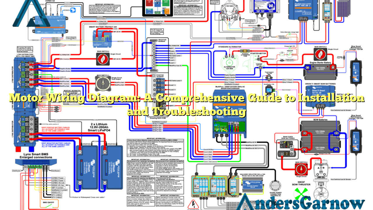
A motor wiring diagram is a detailed schematic representation of the electrical connections and interconnections between various components in an electric motor. It illustrates the path of electrical current and provides crucial information for proper installation, maintenance, and troubleshooting of motors.
A motor wiring diagram typically includes information about the power supply, motor terminals, control circuits, protective devices, and any additional components required for the motor’s operation.
Benefits of Motor Wiring Diagrams
Motor wiring diagrams offer several advantages:
- Clear Visualization: Wiring diagrams provide a clear visual representation of the motor’s electrical connections, aiding in understanding and troubleshooting.
- Enhanced Safety: Proper wiring reduces the risk of electrical hazards, such as short circuits or electric shocks.
- Efficient Troubleshooting: Wiring diagrams facilitate the identification of faulty connections or components, streamlining the troubleshooting process.
- Consistency and Standardization: Wiring diagrams ensure consistent wiring practices, enabling easy replication and maintenance.
- Improved Communication: Wiring diagrams serve as a common language between electricians, technicians, and engineers, promoting effective communication.
Drawbacks of Motor Wiring Diagrams
While motor wiring diagrams are immensely useful, they do have a few limitations:
- Complexity: Wiring diagrams can be complex, especially for individuals with limited electrical expertise.
- Space Constraints: In some cases, fitting all the necessary information within a single diagram can be challenging, leading to overcrowded diagrams.
- Version Control: As motor wiring diagrams evolve with time or modifications, ensuring the latest version is available to all stakeholders can be a logistical challenge.
2. Understanding the Components in a Motor Wiring Diagram
A motor wiring diagram consists of various components, each playing a vital role in the motor’s operation. Let’s explore the key components typically found in a motor wiring diagram:
| Component | Description |
|---|---|
| Power Supply | The source of electrical power for the motor. |
| Motor Terminals | The connection points on the motor where electrical wires are attached. |
| Control Circuits | Circuits that regulate the motor’s operation, including start, stop, and speed control. |
| Protective Devices | Devices such as fuses, circuit breakers, or overload relays that protect the motor from electrical faults. |
| Additional Components | Other components required for specific motor applications, such as capacitors or transformers. |
Continued…
