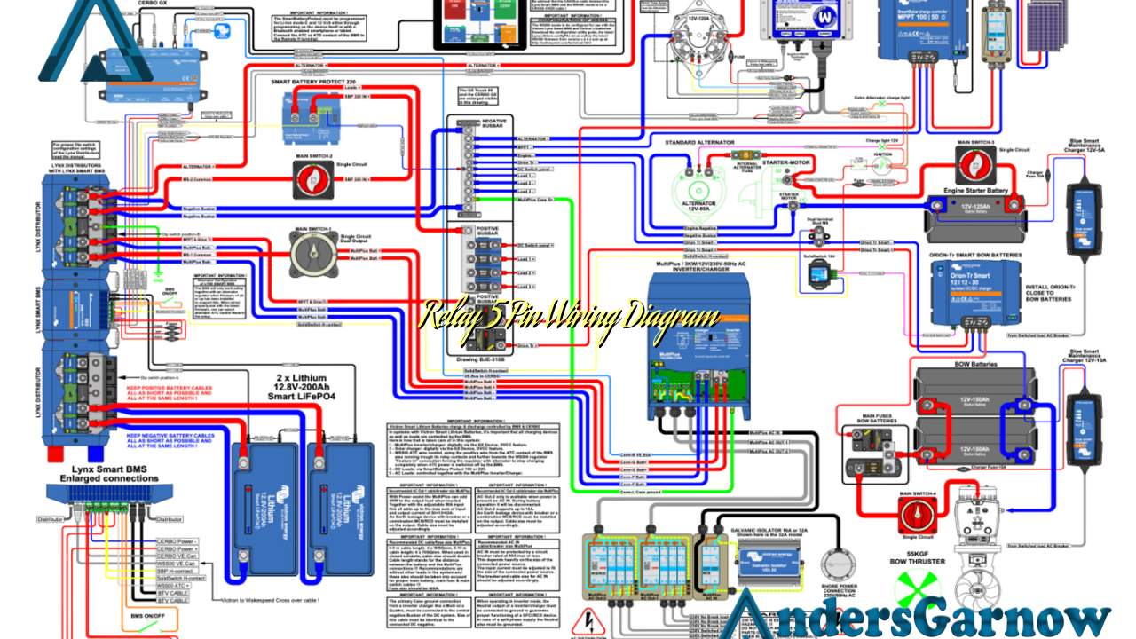
Hello there! In this article, we will delve into the world of relay 5 pin wiring diagrams. A relay is an essential component in electrical systems, allowing the control of high current devices with a low current signal. Understanding the wiring diagram for a 5-pin relay is crucial for properly installing and troubleshooting electrical circuits. So, let’s dive in and explore this topic in detail.
1. What is a Relay?
A relay is an electrically operated switch that uses an electromagnet to mechanically control the switching action. It allows a low power signal to control a higher power circuit, providing isolation and protection to the controlling circuit.
A 5-pin relay consists of five terminals: two for the control circuit and three for the load circuit. The control circuit terminals are typically labeled as “coil positive” and “coil negative,” while the load circuit terminals are labeled as “normally open,” “normally closed,” and “common.”
2. Pin Configuration
The pin configuration of a 5-pin relay may vary depending on the manufacturer, but the most common layout is as follows:
| Terminal | Description |
|---|---|
| Coil Positive (+) | Connects to the positive terminal of the control circuit power supply. |
| Coil Negative (-) | Connects to the negative terminal of the control circuit power supply. |
| Normally Open (NO) | Remains open when the relay is not energized and closes when the relay is energized. |
| Normally Closed (NC) | Remains closed when the relay is not energized and opens when the relay is energized. |
| Common (COM) | Connects to one end of the load circuit. |
3. Wiring a 5-Pin Relay
Now, let’s discuss how to wire a 5-pin relay. The wiring process involves connecting the control circuit and the load circuit to the appropriate terminals of the relay.
To wire a 5-pin relay:
- Connect the positive terminal of the control circuit power supply to the “Coil Positive” terminal of the relay.
- Connect the negative terminal of the control circuit power supply to the “Coil Negative” terminal of the relay.
- Connect one end of the load circuit to the “Common” terminal of the relay.
- If the load circuit needs to be normally open, connect the other end to the “Normally Open” terminal. Otherwise, connect it to the “Normally Closed” terminal.
4. Advantages of a 5-Pin Relay
The use of a 5-pin relay offers several advantages:
- Versatility: A 5-pin relay can be used in various applications, including automotive, industrial, and household systems.
- Isolation: The relay provides isolation between the control circuit and the load circuit, protecting the control circuit from potentially high voltages or currents.
- Switching high currents: A 5-pin relay can handle higher currents than most electronic switches, making it suitable for controlling heavy loads.
5. Disadvantages of a 5-Pin Relay
While a 5-pin relay has several advantages, it also has some limitations:
- Bulky size: Compared to solid-state relays or electronic switches, 5-pin relays are relatively larger in size.
- Reliability: Mechanical relays may have a limited lifespan due to mechanical wear and tear.
- Coil power consumption: The coil of a 5-pin relay requires continuous power to remain energized, consuming some amount of power.
6. Alternative to a 5-Pin Relay
If a 5-pin relay is not suitable for your application, you may consider using a solid-state relay (SSR) as an alternative. SSRs use semiconductor devices to perform the switching action, offering several advantages over mechanical relays, including smaller size, longer lifespan, and faster switching speeds.
FAQs
Q: Can I use a 5-pin relay to control multiple devices?
A: Yes, you can use a 5-pin relay to control multiple devices by connecting them in parallel to the load circuit terminals of the relay.
Q: What is the maximum current rating of a 5-pin relay?
A: The maximum current rating depends on the specific relay model. It is crucial to check the datasheet or specifications provided by the manufacturer to ensure the relay can handle the required current.
Q: How can I test a 5-pin relay?
A: You can test a 5-pin relay using a multimeter. By applying a voltage to the control circuit terminals, you can check if the relay properly switches the load circuit terminals.
Q: Can I use a 5-pin relay in a 12V automotive system?
A: Yes, 5-pin relays are commonly used in automotive systems. However, it is essential to select a relay with the appropriate voltage rating for your specific application.
Q: Are there any safety precautions when working with relays?
A: When working with relays or any electrical components, it is crucial to disconnect the power source before making any connections or modifications. Additionally, following proper wiring practices and using appropriate insulation can help prevent electrical hazards.
Q: Where can I purchase a 5-pin relay?
A: 5-pin relays are widely available at electronics stores, automotive supply shops, and online marketplaces. Ensure to choose a reliable supplier to obtain high-quality relays.
Q: Can I use a 5-pin relay in a low voltage circuit?
A: Yes, 5-pin relays can be used in low voltage circuits, provided that the voltage and current ratings of the relay are suitable for the specific application.
In conclusion, understanding the wiring diagram and operation of a 5-pin relay is crucial for effective control of electrical circuits. While 5-pin relays offer versatility and high current handling capabilities, they also have limitations such as size and mechanical wear. Considering alternatives like solid-state relays can overcome some of these limitations. Remember to follow safety precautions when working with relays and ensure proper selection based on voltage and current requirements. With this knowledge, you can confidently incorporate relay 5-pin wiring diagrams into your electrical projects.

