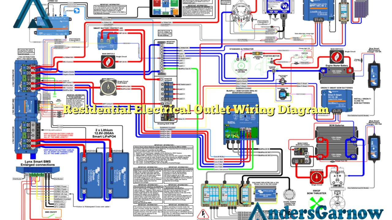
Hello readers, welcome to our comprehensive guide on residential electrical outlet wiring diagrams. In this article, we will provide detailed information on how to properly wire electrical outlets in your home. Understanding the wiring diagram will not only help you install outlets correctly but also ensure the safety and functionality of your electrical system.
1. Importance of a Residential Electrical Outlet Wiring Diagram
A residential electrical outlet wiring diagram is a visual representation of the electrical connections and circuitry in a home. It outlines the path of electrical current from the main electrical panel to each individual outlet, including receptacles, switches, and other devices. This diagram is crucial as it helps electricians, homeowners, and even DIY enthusiasts understand how to wire outlets correctly, ensuring compliance with electrical codes and preventing potential hazards.
2. Understanding the Wiring Diagram
Before we dive into the details, let’s familiarize ourselves with the elements of a typical residential electrical outlet wiring diagram:
| Symbol | Description |
|---|---|
| A | Hot wire (usually black) |
| W | Neutral wire (usually white) |
| G | Ground wire (usually green or bare copper) |
| C | Receptacle |
| S | Switch |
These symbols are used throughout the diagram to represent the various components of the electrical system. The hot wire (A) carries the electrical current from the panel to the outlet, while the neutral wire (W) provides the return path for the current. The ground wire (G) is a safety measure that ensures any excess current is directed safely into the ground. The receptacle (C) represents the outlet itself, and the switch (S) controls the flow of electricity to the outlet.
3. Wiring Outlets in Series
In a residential electrical outlet wiring diagram, outlets can be wired in series or parallel. Wiring outlets in series means that the current flows through each outlet in a daisy chain fashion. This method is commonly used when outlets are located along a single circuit or wall. One advantage of wiring outlets in series is that it requires fewer wires, reducing material and installation costs. However, a major drawback is that if one outlet fails or is overloaded, it can disrupt the flow of electricity to all subsequent outlets in the series.
4. Wiring Outlets in Parallel
On the other hand, wiring outlets in parallel means each outlet is connected directly to the main electrical panel. This method provides each outlet with its own independent circuit, allowing them to operate individually. Wiring outlets in parallel is the preferred method as it offers better reliability and flexibility. If one outlet fails, it does not affect the others. Additionally, each outlet can handle its own load, reducing the risk of overloading the circuit. However, wiring outlets in parallel requires more wires and may be more complex to install compared to wiring in series.
5. Advantages of a Residential Electrical Outlet Wiring Diagram
Using a residential electrical outlet wiring diagram offers several advantages:
- Ensures proper wiring installation
- Helps maintain electrical safety standards
- Prevents electrical hazards and potential fires
- Aids troubleshooting electrical issues
- Allows for future modifications or upgrades
6. Common Mistakes to Avoid
While wiring outlets, it’s important to avoid common mistakes that can compromise the safety and functionality of your electrical system:
- Incorrectly connecting the hot, neutral, and ground wires
- Overloading circuits with too many devices
- Using inadequate wire gauge for the circuit’s amperage
- Not using proper electrical connectors or wire nuts
- Failing to secure wires properly
7. Alternative Residential Electrical Outlet Wiring Diagram
Another alternative for residential electrical outlet wiring is the use of AFCI (Arc Fault Circuit Interrupter) outlets. AFCI outlets provide enhanced protection against electrical fires by detecting dangerous arc faults and shutting off the power. These outlets have a different wiring diagram compared to standard outlets, as they require an additional AFCI circuit breaker in the main electrical panel. It is recommended to consult a licensed electrician when installing AFCI outlets.
8. Frequently Asked Questions (FAQ)
Q: Can I install electrical outlets without a wiring diagram?
A: While it is possible to install outlets without a wiring diagram, it is highly recommended to use one. A wiring diagram ensures proper connections and compliance with electrical codes, minimizing the risk of electrical hazards.
Q: Can I use different wire colors for hot, neutral, and ground?
A: It is crucial to follow standard wire color coding for electrical installations. Using different wire colors can lead to confusion and potential safety hazards. Hot wires are typically black, neutral wires are white, and ground wires are green or bare copper.
Conclusion
In conclusion, understanding and using a residential electrical outlet wiring diagram is essential for safe and proper installation of outlets in your home. Whether you choose to wire outlets in series or parallel, always follow electrical codes and best practices to ensure the functionality and safety of your electrical system. Remember to consult a licensed electrician for any complex wiring tasks and when installing specialized outlets like AFCIs. Stay informed, stay safe!

