Hello readers,
1. Introduction to Rocker Switch Wiring Diagram
A rocker switch is a type of electrical switch that is widely used in various applications, including automotive, marine, household, and industrial. It is called a rocker switch because of its unique design that resembles a rocking motion when it is toggled on or off. Understanding the wiring diagram of a rocker switch is essential for proper installation and ensuring its functionality.
2. Components of a Rocker Switch
A typical rocker switch consists of several components, including the switch body, terminal connectors, and the actuator. The switch body houses the internal mechanism and electrical contacts, while the terminal connectors provide the connection points for the electrical wires. The actuator is the part of the switch that is pressed or flipped to toggle the switch on or off.
3. Wiring Diagram for a Rocker Switch
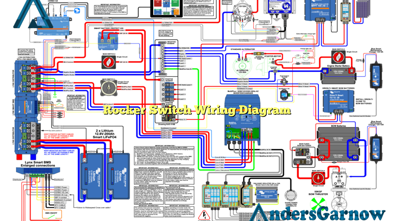
The wiring diagram of a rocker switch may vary depending on its configuration, such as the number of poles and throws. However, the basic wiring principle remains the same. It typically includes the power source, load, and ground connections. The power source is connected to one terminal of the switch, while the load is connected to another terminal. The remaining terminal is connected to the ground or earth connection.
4. Advantages of Using a Rocker Switch
Rocker switches offer several advantages over other types of switches. Firstly, they are easy to operate with a simple up or down motion. Secondly, they provide a clear indication of the switch’s status with the help of the rocker’s position. Additionally, rocker switches are durable and can handle high electrical loads, making them suitable for various applications.
5. Disadvantages of Using a Rocker Switch
Although rocker switches have numerous advantages, they also have a few limitations. One major disadvantage is their relatively larger size compared to other types of switches, which can be a constraint in certain applications with limited space. Additionally, rocker switches may not be as suitable for precise or sensitive control due to their binary on-off operation.
6. Alternative Wiring Diagram for a Rocker Switch
As an alternative to the standard wiring diagram, a momentary rocker switch can be wired differently. Instead of connecting the load to one terminal, it is connected to both terminals. This configuration allows the switch to act as a push-button, where the load is powered as long as the switch is held down. Releasing the switch will turn off the load.
7. Rocker Switch Wiring Diagram Table
| Terminal | Function |
|---|---|
| 1 | Power Source |
| 2 | Load |
| 3 | Ground |
8. Frequently Asked Questions (FAQ) about Rocker Switch Wiring Diagram
Q: Can I use a rocker switch for both AC and DC applications?
A: Yes, rocker switches are suitable for both AC and DC applications as long as the voltage and current ratings are within the switch’s specifications.
Q: How do I know which terminal is which in a rocker switch?
A: Most rocker switches are labeled or have markings near the terminals indicating their function. If not, you can refer to the manufacturer’s datasheet or documentation for the specific switch model.
Q: Can I wire multiple rocker switches in parallel?
A: Yes, you can wire multiple rocker switches in parallel as long as you ensure the power source and ground connections are properly connected.
Conclusion
In conclusion, understanding the wiring diagram of a rocker switch is crucial for a successful installation and operation. Rocker switches offer ease of use, durability, and clear indication of their status. However, they may have size limitations and are not suitable for precise control. It is essential to follow the specific wiring diagram provided by the manufacturer or consult a professional if needed. By utilizing the provided table and alternative wiring diagram, you can confidently install and utilize rocker switches in various applications.

