Hello readers! In this article, we will delve into the world of schematic diagrams, exploring their significance, uses, advantages, and disadvantages. So, let’s begin our journey into the realm of schematic diagrams!
1. Understanding Schematic Diagrams
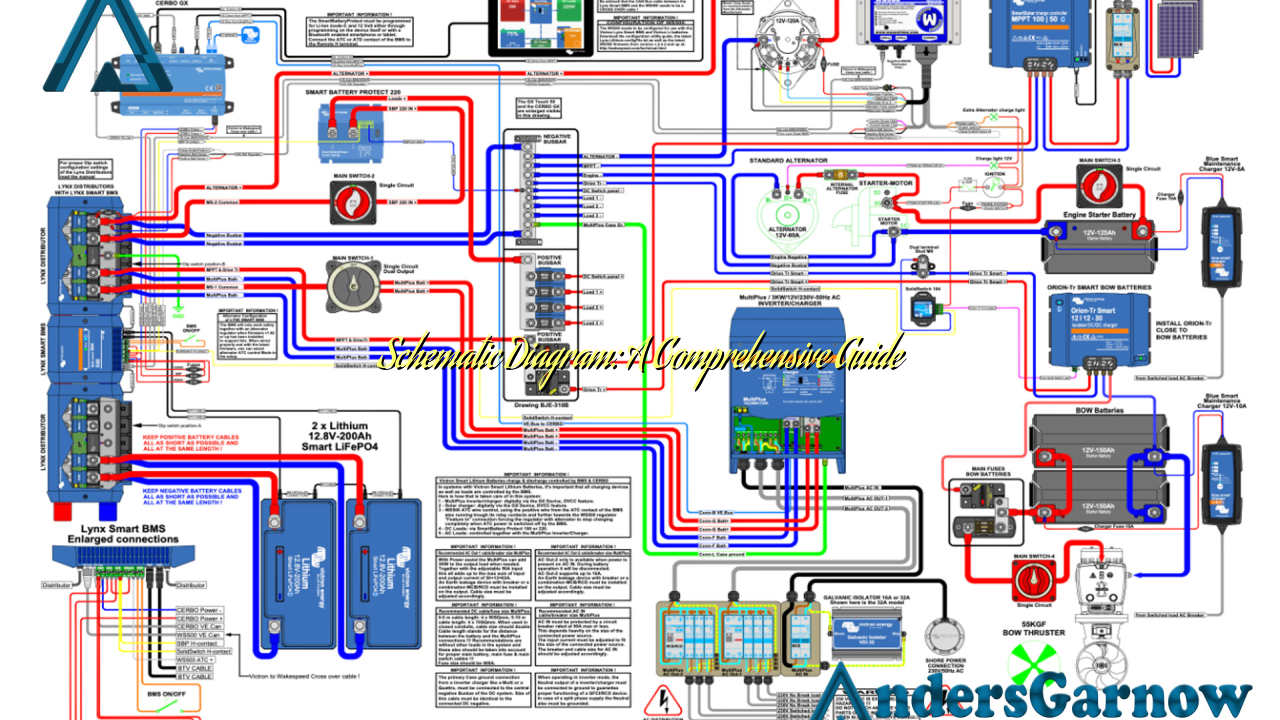
Schematic diagrams are graphical representations that illustrate the functioning and connections of electronic circuits using standardized symbols. These diagrams play a crucial role in understanding complex systems and assisting in the design, troubleshooting, and maintenance of electronic devices.
2. The Importance of Schematic Diagrams
Schematic diagrams serve as a universal language for electrical and electronic engineers, technicians, and enthusiasts. They provide a visual representation of how components are interconnected, allowing for easy comprehension and analysis of circuits. These diagrams enable efficient troubleshooting, saving time and resources in identifying faults or malfunctions.
3. Advantages of Schematic Diagrams
Schematic diagrams offer several advantages:
| Advantages | Explanation |
|---|---|
| Ease of Understanding | The standardized symbols and clear layout of schematic diagrams make it easy for individuals to grasp complex circuitry. |
| Efficient Troubleshooting | By following the schematic diagram, technicians can quickly identify and rectify faults in electronic systems. |
| Design and Prototyping | Schematic diagrams aid in the design and prototyping of electronic circuits, ensuring accurate implementation. |
| Documentation | These diagrams serve as valuable documentation for future reference, repairs, or modifications. |
4. Disadvantages of Schematic Diagrams
While schematic diagrams are highly useful, they also have certain limitations:
| Disadvantages | Explanation |
|---|---|
| Complexity | Schematic diagrams can become complex and challenging to interpret in intricate electronic systems. |
| Learning Curve | Understanding and creating schematic diagrams require knowledge of standardized symbols and circuitry principles. |
| Space Limitations | In large systems, fitting an entire circuit into a single schematic diagram may become impractical. |
5. Alternatives to Schematic Diagrams
While schematic diagrams are widely used, alternative methods exist for representing circuitry:
Block Diagrams: Block diagrams provide a high-level overview of a system, focusing on its main components and their interconnections. They are useful for understanding system architecture but lack the detailed information of a schematic diagram.
Breadboard Layouts: Breadboard layouts are physical representations of circuits using actual components. They are commonly used in prototyping and experimentation stages to test circuit designs before creating a schematic diagram.
6. Frequently Asked Questions (FAQ)
Q: Can I use a schematic diagram to repair electronic devices?
A: Yes, schematic diagrams are valuable tools for troubleshooting and repairing electronic devices. They provide insights into the circuitry and aid in identifying faulty components.
Q: Are schematic diagrams only used in the field of electronics?
A: While schematic diagrams are primarily associated with electronics, they can also be used in other fields such as mechanical engineering, architecture, and even for representing flowcharts or processes.
Conclusion
In conclusion, schematic diagrams are essential visual representations of electronic circuits, enabling a deeper understanding of complex systems. While they have advantages such as ease of understanding and efficient troubleshooting, they also come with limitations like complexity and a learning curve. However, despite their drawbacks, schematic diagrams remain an invaluable tool for engineers, technicians, and enthusiasts in the world of electronics.
