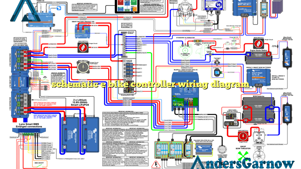
Hello! Welcome to our article on the schematic e bike controller wiring diagram. In this comprehensive guide, we will discuss the various aspects of e bike controller wiring and provide you with a detailed understanding of the schematic diagram. Whether you are a beginner or an experienced enthusiast, this article will help you navigate through the complexities of e bike controller wiring.
1. Understanding the Basics
Before we delve into the schematic e bike controller wiring diagram, let’s briefly discuss the basics. The e bike controller is a crucial component that controls the motor, throttle, and other electronic features of an electric bike. It acts as the brain of the e bike, providing power and regulating various functions.
The wiring diagram is a visual representation of how the different components of the e bike controller are interconnected. It shows the connections between the battery, motor, throttle, brake sensors, and other essential parts. Understanding this diagram is essential for troubleshooting, upgrading, or modifying your e bike’s electrical system.
2. Components Involved
To fully comprehend the schematic e bike controller wiring diagram, let’s explore the key components involved:
| Component | Description |
|---|---|
| Battery | Provides power to the e bike controller |
| Motor | Converts electrical energy into mechanical energy to propel the bike |
| Throttle | Controls the speed of the electric bike |
| Brake Sensors | Ensure the motor stops when the brakes are engaged |
| Controller | Regulates the flow of electricity and controls various functions |
3. Schematic E Bike Controller Wiring Diagram
Now let’s move on to the main focus of our article – the schematic e bike controller wiring diagram. This diagram provides a visual representation of how the various components are connected. It includes symbols and labels that help you identify each part and understand their interconnections.
Although specific wiring diagrams may vary depending on the brand and model of your e bike controller, the basic principles remain the same. Here is a simplified version of a typical e bike controller wiring diagram:
It is important to note that this is a general representation, and you should always refer to the manufacturer’s instructions or specific wiring diagram for your controller to ensure accuracy.
4. Benefits of Understanding the Wiring Diagram
Understanding the schematic e bike controller wiring diagram offers several benefits. Let’s take a look at some of them:
a) Easy Troubleshooting: With a clear understanding of the wiring diagram, you can quickly identify and resolve any electrical issues that may arise in your e bike controller system.
b) Upgrades and Modifications: The wiring diagram enables you to make upgrades or modifications to your e bike controller, such as adding a display or adjusting the throttle response, with ease and confidence.
c) DIY Repairs: Armed with the knowledge of the wiring diagram, you can confidently undertake DIY repairs and maintenance tasks, saving both time and money.
5. Common Challenges and Solutions
While working with the e bike controller wiring, you may encounter some challenges. Here are a few common ones along with their solutions:
a) Loose Connections: Loose or faulty connections can disrupt the flow of electricity. Ensure that all connections are secure and properly insulated.
b) Incorrect Wiring: Incorrectly wiring the components can lead to malfunctioning or damage. Always double-check the wiring diagram and follow the manufacturer’s instructions carefully.
c) Compatibility Issues: Ensure that the components you are using are compatible with each other and the e bike controller. Check the voltage and power requirements to avoid any compatibility issues.
6. Alternative Wiring Options
While the schematic e bike controller wiring diagram we discussed earlier is a common and reliable option, there are alternative wiring options available as well. These alternative diagrams may cater to specific e bike models or advanced features. It is crucial to refer to the manufacturer’s instructions or specialized resources when using alternative wiring options.
Conclusion
In conclusion, understanding the schematic e bike controller wiring diagram is vital for any electric bike enthusiast. It allows you to troubleshoot, upgrade, and modify your e bike controller system with confidence. By familiarizing yourself with the components, their connections, and common challenges, you can ensure a smooth and efficient riding experience. Remember to always refer to the manufacturer’s instructions and specific wiring diagrams for your e bike controller to ensure accurate connections and optimal performance.
Frequently Asked Questions (FAQ)
Q: Can I modify my e bike controller wiring without professional assistance?
A: Yes, you can modify your e bike controller wiring if you have a good understanding of the schematic diagram and have experience working with electrical systems. However, it is recommended to seek professional assistance if you are unsure or lack the necessary expertise.
Q: Are there any safety precautions to consider when working with e bike controller wiring?
A: Absolutely! When working with e bike controller wiring, always ensure that the power source is disconnected, wear appropriate safety gear such as gloves and goggles, and follow proper electrical safety guidelines. It is also crucial to check the local regulations and laws regarding e bike modifications.
Q: Can I use the same wiring diagram for all e bike controller models?
A: While the basic principles of e bike controller wiring remain the same, there may be slight variations in the wiring diagrams of different models. Always refer to the manufacturer’s instructions or specific wiring diagram for your e bike controller model to ensure accuracy.

