Hello and welcome to our in-depth article on schematics diagrams! In this guide, we will delve into the world of schematics diagrams, their importance, advantages, and disadvantages, as well as provide alternative options. Whether you are an engineer, electrician, or simply curious about the inner workings of various systems, this article is for you.
1. What are Schematics Diagrams?
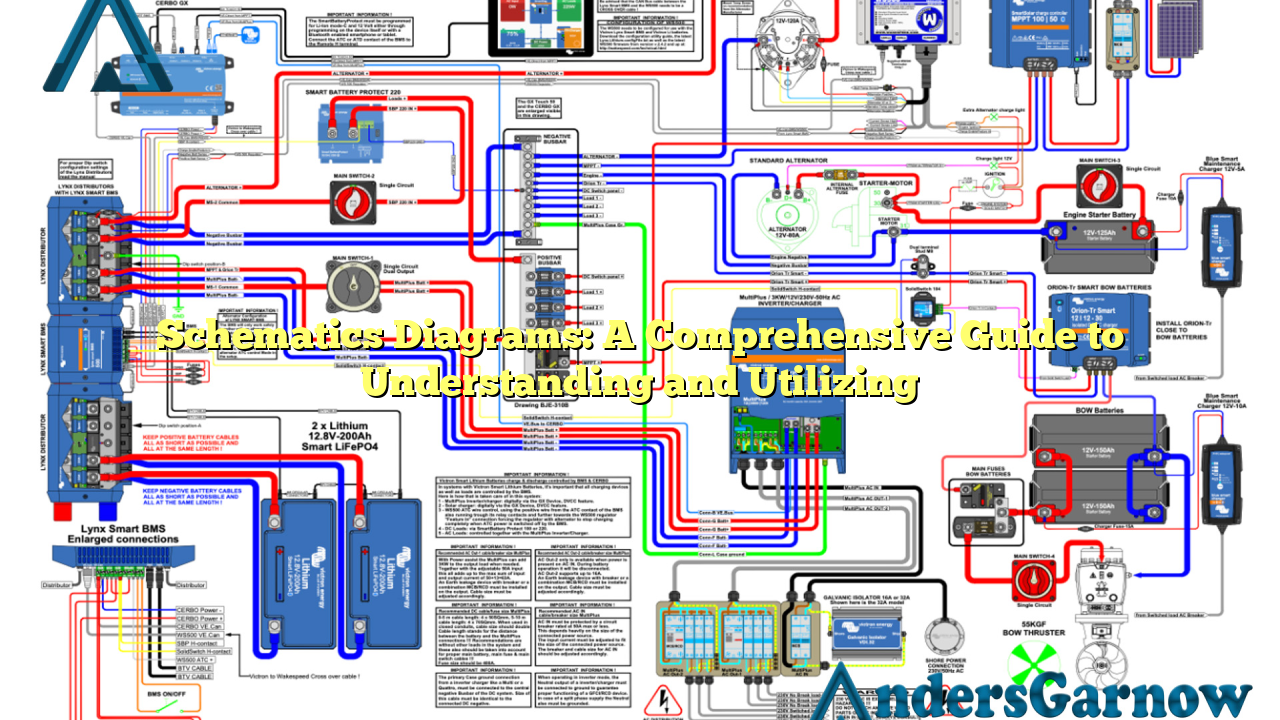
Schematics diagrams are graphical representations of electrical circuits or systems. They use standardized symbols to illustrate the connections between different components and their functions. These diagrams provide a visual guide to understanding the flow of electricity and how each component interacts with others within a system.
2. The Importance of Schematics Diagrams
Schematics diagrams play a crucial role in various industries, such as electronics, telecommunications, and automotive. They serve as a blueprint for engineers and technicians, enabling them to design, troubleshoot, and repair complex systems effectively. These diagrams ensure accurate communication and documentation of circuitry, reducing errors and enhancing efficiency in the development and maintenance processes.
3. Advantages of Schematics Diagrams
There are several advantages to utilizing schematics diagrams:
- Clarity: Schematics diagrams provide a clear and concise overview of a system, making it easier to understand and interpret.
- Troubleshooting: When a system malfunctions, schematics diagrams act as a troubleshooting tool, allowing technicians to identify faulty components quickly.
- Standardization: The use of standardized symbols in schematics diagrams ensures universal understanding across different industries and regions.
- Efficiency: By visually representing complex circuitry, schematics diagrams improve efficiency in system design, repair, and maintenance processes.
4. Disadvantages of Schematics Diagrams
While schematics diagrams offer numerous benefits, they also have some limitations:
- Complexity: Understanding and creating schematics diagrams require a certain level of technical knowledge and expertise.
- Space Limitations: In complex systems, schematics diagrams can become crowded and challenging to read due to the large number of components and connections.
- Updates: As systems evolve and components change, schematics diagrams need to be frequently updated to reflect the latest configurations.
5. Alternatives to Schematics Diagrams
While schematics diagrams are widely used, there are alternative methods for representing electrical circuits:
- Breadboards: Breadboards are prototyping tools that allow for quick and temporary circuit assembly.
- Block Diagrams: Block diagrams focus on the functional relationships between components, rather than their detailed connections.
- Circuit Simulators: These software tools enable engineers to simulate and analyze circuits without the need for physical components.
6. Schematics Diagrams: A Detailed Analysis
| Aspect | Details |
|---|---|
| Purpose | Illustrate electrical circuits and systems |
| Components | Resistors, capacitors, diodes, transistors, etc. |
| Symbols | Standardized symbols for consistent representation |
| Connections | Lines depicting electrical connections between components |
| Layout | Logical arrangement of components for clarity |
7. Frequently Asked Questions (FAQ)
Q: Are schematics diagrams only used in electrical engineering?
A: While schematics diagrams are commonly used in electrical engineering, they are also utilized in various other fields such as telecommunications, automotive, and computer hardware.
Q: Can I create my own schematics diagrams?
A: Yes, with the necessary knowledge and software tools, you can create your own schematics diagrams. However, it is essential to ensure accuracy and adherence to industry standards.
Q: How often should schematics diagrams be updated?
A: Schematics diagrams should be updated whenever there are changes in the system configuration or components. Regular review and updates are crucial to maintaining accuracy and reliability.
Q: Are there any online resources available for learning schematics diagrams?
A: Yes, there are numerous online tutorials, courses, and forums dedicated to teaching schematics diagrams. These resources provide a comprehensive guide for beginners and advanced learners.
Q: Can schematics diagrams be exported to other file formats?
A: Yes, schematics diagrams can be exported to various file formats, such as PDF, PNG, or SVG, to facilitate sharing, printing, and integration into documentation.
Q: Is it possible to simulate circuits using schematics diagrams?
A: While schematics diagrams provide a visual representation of circuits, they do not have built-in simulation capabilities. However, circuit simulation software can import schematics diagrams for analysis and testing.
Q: Are there any industry standards for schematics diagrams?
A: Yes, several industry standards, such as ANSI/IEEE Std 91-1984, IEC 60617, and JIC Standard, define the symbols and conventions used in schematics diagrams.
Q: Can I use schematics diagrams for patent applications?
A: Schematics diagrams can be included in patent applications to illustrate the technical aspects and functionality of an invention. However, it is crucial to consult with a patent attorney to ensure compliance with the specific requirements of the patent office.
8. Conclusion
In conclusion, schematics diagrams are invaluable tools for understanding, designing, and maintaining electrical circuits and systems. Their visual representation enhances clarity, troubleshooting, and standardization in various industries. While they have some limitations, alternative methods and continuous updates address these challenges. By harnessing the power of schematics diagrams, engineers and technicians can effectively navigate the complexities of modern electrical systems.
