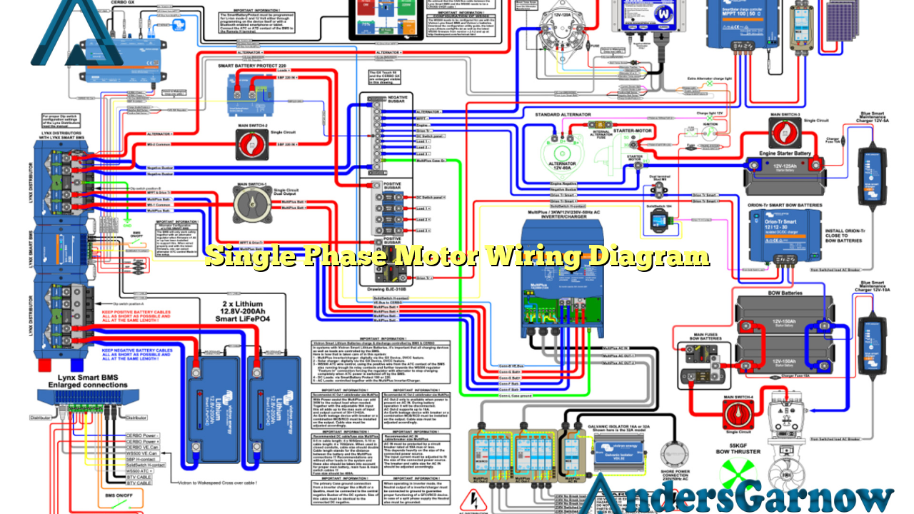
Hello and welcome to our detailed guide on single phase motor wiring diagram. In this article, we will provide you with a comprehensive explanation of the wiring diagram for single phase motors. Understanding how to properly wire a single phase motor is essential for anyone working with electrical systems. So, let’s dive in and explore this topic further.
1. Introduction to Single Phase Motor Wiring Diagram
Single phase motors are commonly used in various applications such as household appliances, power tools, and small machinery. These motors operate on a single phase power supply and require specific wiring connections to function properly. The wiring diagram provides a visual representation of the electrical connections required for the motor to operate safely and efficiently.
It is important to note that single phase motors have different wiring configurations based on their horsepower ratings and operating voltages. The most common types of single phase motor wiring diagrams include capacitor start, capacitor run, split-phase, and shaded pole motors.
2. Capacitor Start Motor Wiring Diagram
The capacitor start motor is a popular type of single phase motor used in applications where high starting torque is required. This motor utilizes a start capacitor to provide the necessary starting torque during the motor’s initial startup. The wiring diagram for a capacitor start motor includes connections for the main winding, start winding, capacitor, and power supply.
One of the advantages of a capacitor start motor is its ability to handle heavy loads and provide high starting torque. However, one drawback is that it requires a separate starting winding and a larger physical size due to the additional components.
3. Capacitor Run Motor Wiring Diagram
The capacitor run motor is another type of single phase motor commonly used in applications where continuous operation is required. This motor utilizes a run capacitor to improve its running efficiency and power factor. The wiring diagram for a capacitor run motor includes connections for the main winding, run winding, capacitor, and power supply.
One of the advantages of a capacitor run motor is its improved efficiency and power factor, resulting in lower energy consumption. However, it may have a lower starting torque compared to a capacitor start motor.
4. Split-Phase Motor Wiring Diagram
The split-phase motor is a type of single phase motor that is widely used in residential applications such as fans, pumps, and air conditioners. This motor utilizes a centrifugal switch to create a phase shift between the main winding and the start winding, enabling the motor to start and run efficiently. The wiring diagram for a split-phase motor includes connections for the main winding, start winding, centrifugal switch, and power supply.
One of the advantages of a split-phase motor is its simplicity and cost-effectiveness. However, it may have lower efficiency and starting torque compared to other types of single phase motors.
5. Shaded Pole Motor Wiring Diagram
The shaded pole motor is a simple and inexpensive type of single phase motor commonly used in small appliances such as fans, blowers, and refrigerators. This motor utilizes a shading coil to create a rotating magnetic field, enabling the motor to start and run. The wiring diagram for a shaded pole motor includes connections for the main winding, shading coil, and power supply.
One of the advantages of a shaded pole motor is its simplicity and low cost. However, it has low efficiency and starting torque, making it suitable for low-power applications.
6. Other Alternatives for Single Phase Motor Wiring Diagram
Aside from the aforementioned types of single phase motors, there are other alternatives available for specific applications. These include permanent split capacitor (PSC) motors, repulsion motors, and universal motors. Each alternative has its own unique wiring diagram and characteristics, catering to different requirements and operating conditions.
7. Single Phase Motor Wiring Diagram Table
| Motor Type | Main Winding | Start Winding | Run Capacitor | Shading Coil | Centrifugal Switch |
|---|---|---|---|---|---|
| Capacitor Start | Connected | Connected | Required | Not Required | Not Required |
| Capacitor Run | Connected | Not Required | Required | Not Required | Not Required |
| Split-Phase | Connected | Connected | Not Required | Not Required | Required |
| Shaded Pole | Connected | Not Required | Not Required | Required | Not Required |
8. Frequently Asked Questions (FAQ) – Single Phase Motor Wiring Diagram
Q: What is the purpose of a wiring diagram for single phase motors?
A: The wiring diagram provides a visual representation of the electrical connections required for the motor to operate safely and efficiently.
Q: Are there different wiring diagrams for single phase motors?
A: Yes, different types of single phase motors have different wiring configurations based on their horsepower ratings and operating voltages.
Q: What are the advantages of a capacitor start motor?
A: Capacitor start motors provide high starting torque, making them suitable for applications that require heavy loads.
Q: What are the advantages of a capacitor run motor?
A: Capacitor run motors have improved efficiency and power factor, resulting in lower energy consumption.
Q: What are the advantages of a split-phase motor?
A: Split-phase motors are simple and cost-effective, making them suitable for residential applications.
Q: What are the advantages of a shaded pole motor?
A: Shaded pole motors are simple and inexpensive, making them suitable for low-power applications.
Conclusion
In conclusion, understanding the wiring diagram for single phase motors is crucial for anyone working with electrical systems. It allows for safe and efficient operation of these motors in various applications. Whether you are dealing with a capacitor start, capacitor run, split-phase, or shaded pole motor, knowing the correct wiring connections and their advantages and disadvantages is essential. We hope this guide has provided you with valuable insights and knowledge on single phase motor wiring diagrams.

