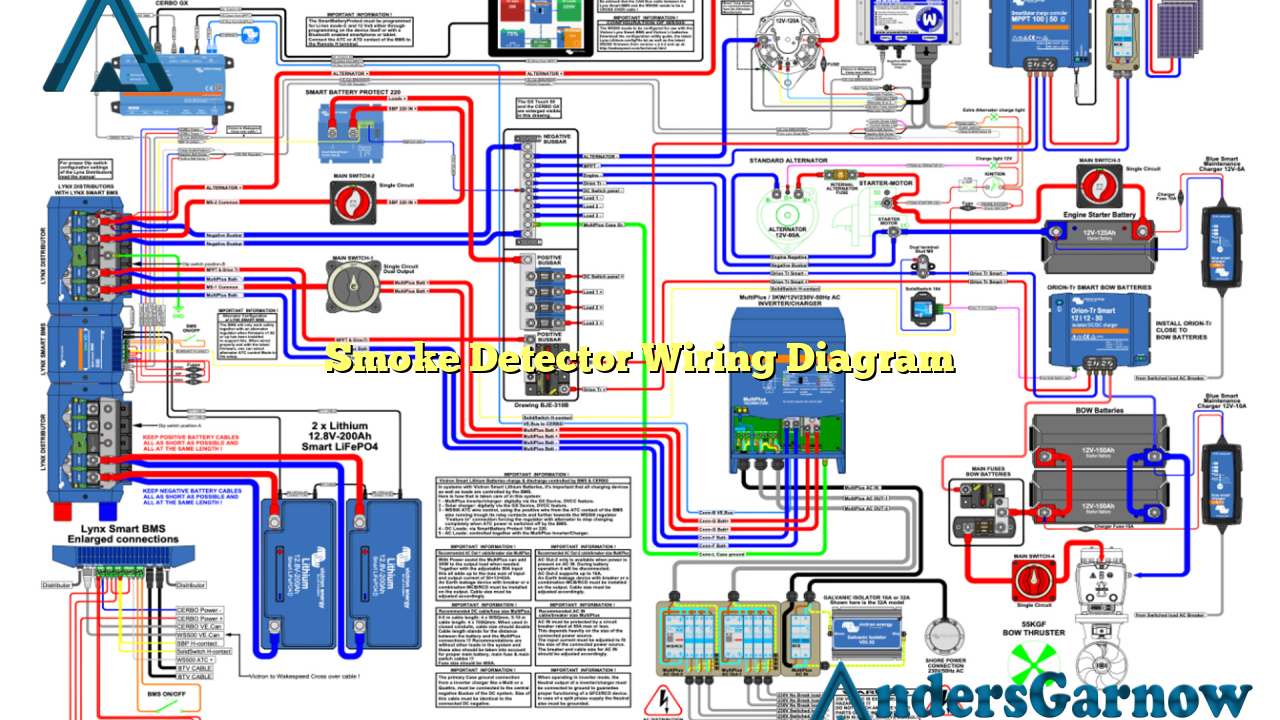
Hello and welcome to our comprehensive guide on smoke detector wiring diagrams. In this article, we will provide you with detailed information about smoke detector wiring diagrams, including their benefits, drawbacks, and alternative options. We will also present a table containing all the necessary information about smoke detector wiring diagrams. So, let’s dive in and explore everything you need to know!
1. Understanding Smoke Detectors
Before we delve into the wiring diagrams, let’s first understand what smoke detectors are and why they are essential for your safety. Smoke detectors are electronic devices designed to detect smoke in residential and commercial buildings. They play a crucial role in alerting occupants about potential fire hazards, allowing them to evacuate the premises timely.
2. Importance of Proper Wiring
Proper wiring is vital for smoke detectors to function effectively. It ensures that the detectors receive power and are interconnected for synchronized operation. Incorrect wiring can lead to malfunctions, false alarms, or even complete failure of the smoke detection system. Therefore, it is crucial to follow the appropriate wiring diagram provided by the manufacturer.
3. Basic Smoke Detector Wiring Diagram
The basic smoke detector wiring diagram consists of three main components: the power source, interconnecting wires, and the smoke detectors themselves. The power source, usually the electrical panel, supplies the detectors with electricity. The interconnecting wires connect all the detectors in the building to ensure they all sound an alarm simultaneously when smoke is detected.
It is important to note that there are two types of smoke detector wiring: series wiring and parallel wiring. In series wiring, all detectors are connected in a single circuit, while in parallel wiring, each detector is connected separately to the power source.
4. Series Wiring Diagram
In a series wiring diagram, all smoke detectors are connected in a loop, creating a continuous circuit. The power source connects to the first detector, and then a wire runs from the first detector to the second, and so on. This wiring configuration ensures that if one detector detects smoke and triggers an alarm, all the other detectors will also sound.
One advantage of series wiring is that it requires less cabling, making it more cost-effective for larger buildings. However, a drawback is that if there is a break in the circuit, such as a disconnected wire, all detectors after the break will not function.
5. Parallel Wiring Diagram
In a parallel wiring diagram, each smoke detector is connected individually to the power source. This means that if one detector triggers an alarm, only that specific detector will sound, while the others remain silent. This wiring configuration is commonly used in residential settings.
One advantage of parallel wiring is that it ensures the continuity of operation even if one detector malfunctions or is disconnected. However, it requires more cabling compared to series wiring, which may increase installation costs.
6. Combination Wiring Diagram
Combination wiring diagrams combine both series and parallel wiring methods. This allows for a more flexible and efficient smoke detection system. For example, the detectors on each floor can be wired in parallel, while the floors themselves are connected in series. This configuration provides the benefits of both wiring methods.
7. Alternative Options
While traditional hardwired smoke detectors are widely used, there are alternative options available. One popular alternative is wireless smoke detectors. These detectors use wireless technology to communicate with each other and do not require any wiring. They are easy to install and can be interconnected for synchronized operation.
Another alternative is the use of interconnected battery-operated smoke detectors. These detectors are not hardwired but can still be interconnected wirelessly. They are suitable for buildings without access to power wiring or for situations where wiring is not feasible.
8. Smoke Detector Wiring Diagram Table
| Component | Series Wiring | Parallel Wiring | Combination Wiring |
|---|---|---|---|
| Power Source | Connected in series | Connected in parallel | Connected in series and parallel |
| Interconnecting Wires | Single circuit loop | Individual connections | Combination of series and parallel connections |
| Alarm Activation | All detectors sound | Only triggered detector sounds | Depends on the configuration |
| Cost | Lower cabling cost | More cabling required | Varies depending on the configuration |
9. Frequently Asked Questions (FAQ)
Q: Can I mix different types of smoke detectors in a single wiring system?
A: It is recommended to use smoke detectors of the same type and model to ensure compatibility and proper functioning. Mixing different types may result in inconsistent performance.
Q: Is it necessary to hire a professional electrician for smoke detector wiring?
A: While it is possible to install smoke detectors yourself, it is highly recommended to consult a professional electrician to ensure correct wiring and compliance with local building codes.
Q: How often should smoke detectors be tested?
A: Smoke detectors should be tested monthly to ensure they are functioning correctly. Additionally, batteries should be replaced annually, or according to the manufacturer’s recommendations.
Conclusion
In conclusion, proper wiring is crucial for the effective operation of smoke detectors. Whether you opt for series, parallel, or combination wiring, it is essential to follow the manufacturer’s guidelines and local building codes. Consider the advantages and disadvantages of each wiring method, and choose the one that best suits your needs. Additionally, explore alternative options such as wireless or battery-operated interconnected smoke detectors. Remember to regularly test and maintain your smoke detectors to ensure your safety and peace of mind.

