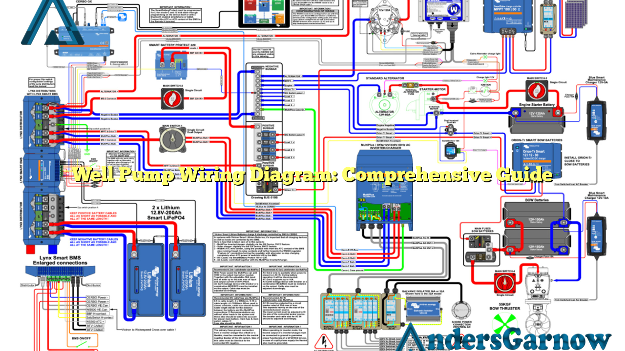
Hello, dear readers! Today, we are going to delve into the intricate world of well pump wiring diagram. Whether you are an experienced electrician or a homeowner seeking to understand the wiring system of your well pump, this article will provide you with a comprehensive guide. So, let’s get started!
1. Understanding the Basics of Well Pump Wiring Diagram
Before we dive into the details, it is essential to have a basic understanding of the well pump wiring diagram. A well pump is a device that extracts water from an underground water source, such as a well or a borehole. The wiring diagram illustrates the electrical connections and components involved in the operation of the well pump system.
The diagram typically includes information about power supply connections, control box connections, pressure switch connections, ground connections, and other relevant electrical components. It serves as a roadmap for electricians to install, troubleshoot, and maintain the well pump system.
Advantages of Well Pump Wiring Diagram
The well pump wiring diagram offers several advantages, including:
- Clear Understanding: The diagram provides a clear visual representation of the electrical connections, making it easier to understand the system.
- Troubleshooting: In case of any issues or malfunctions, the diagram helps electricians identify the problem areas and rectify them efficiently.
- Compliance with Regulations: Following the well pump wiring diagram ensures compliance with electrical codes and safety regulations.
- Efficient Maintenance: With the diagram, routine maintenance tasks become more efficient as electricians can quickly identify and inspect the relevant components.
Disadvantages of Well Pump Wiring Diagram
While the well pump wiring diagram is an invaluable tool, it also has certain limitations:
- Complexity: Understanding and interpreting the diagram requires technical knowledge and expertise.
- Specificity: Each well pump system may have unique wiring requirements, making it crucial to refer to the specific diagram for accurate connections.
- Updates: With technological advancements, the wiring diagram may need updates to accommodate new components or system modifications.
2. Detailed Components of Well Pump Wiring Diagram
The well pump wiring diagram consists of various components, each playing a crucial role in the system’s operation. Let’s explore them in detail:
| Component | Description |
|---|---|
| Power Supply | Provides electrical energy to the well pump system. It typically connects to a circuit breaker or a fuse box. |
| Control Box | Acts as the brain of the well pump system, regulating the pump’s operation based on water demand. |
| Pressure Switch | Detects the water pressure and triggers the pump to start or stop based on the set pressure thresholds. |
| Motor Starter | Starts and stops the electric motor that drives the pump’s operation. |
| Capacitor | Assists the electric motor in starting by providing an additional burst of power. |
| Grounding System | Ensures the safety of the well pump system by providing a path for electrical faults to dissipate. |
| Float Switch | Detects the water level in a storage tank and controls the operation of the pump accordingly. |
| Check Valve | Prevents backflow of water into the well when the pump is not in operation. |
| Pressure Tank | Stores pressurized water to meet the demand without frequent pump cycling. |
3. Alternatives to Well Pump Wiring Diagram
While the well pump wiring diagram is widely used, there are alternative methods to understand and install well pump systems:
- Manufacturer’s Instructions: Well pump manufacturers often provide detailed installation manuals with step-by-step instructions and diagrams specific to their products.
- Professional Assistance: Hiring a licensed electrician or well pump technician ensures accurate installation and adherence to safety regulations.
4. Frequently Asked Questions (FAQ) about Well Pump Wiring Diagram
Q: Can I install a well pump system without referring to the wiring diagram?
A: It is highly recommended to refer to the wiring diagram to ensure proper installation and safe operation of the well pump system. Skipping this step may result in electrical hazards or system malfunctions.
Q: How often should I update the well pump wiring diagram?
A: The well pump wiring diagram should be updated whenever there are modifications to the system, such as the addition of new components or changes in the electrical connections. Regular review and update ensure accurate documentation.
In Conclusion
Understanding the well pump wiring diagram is essential for a safe and efficient well pump system installation and maintenance. It provides a comprehensive overview of the electrical connections and components involved, ensuring compliance with regulations and facilitating troubleshooting. Remember, when in doubt, always consult a professional to ensure the proper functioning of your well pump system.

