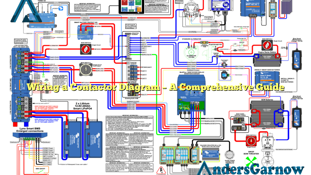
Hello readers! In this article, we will discuss everything you need to know about wiring a contactor diagram. Whether you are a professional electrician or a DIY enthusiast, understanding the wiring of a contactor is crucial for a safe and efficient electrical system. So, let’s dive into the details and explore the world of contactor diagrams!
1. What is a Contactor?
A contactor is an electrical device used for switching an electrical circuit on or off. It consists of a coil, contacts, and a mechanical assembly. When the coil is energized, it creates a magnetic field that attracts the contacts, closing the circuit. Contactor diagrams provide a visual representation of the wiring connections required for proper functioning of the contactor.
2. Advantages of Using a Contactor Diagram
Contactor diagrams offer several advantages, including:
- Clarity: A well-drawn contactor diagram provides a clear representation of the wiring connections, making it easier to understand and follow.
- Efficiency: By following a contactor diagram, you can ensure that the wiring connections are correct, reducing the risk of electrical faults and improving the efficiency of your electrical system.
- Safe Operation: Contactors play a crucial role in the safe operation of electrical systems. A contactor diagram helps in proper installation, reducing the chances of accidents or malfunctions.
3. Understanding the Contactor Diagram
A contactor diagram consists of various symbols and lines that represent different electrical components and their connections. Here are some key elements you will find in a typical contactor diagram:
- Coil: Represented by a zigzag line, the coil is the primary component that creates the magnetic field to control the contacts.
- Contacts: Depicted by parallel lines, the contacts are the points where the electrical circuit is opened or closed.
- Control Circuit: This circuit includes the coil, power supply, and control devices such as switches or relays.
- Main Circuit: The main circuit comprises the power supply, load, and contactor contacts that control the flow of electricity.
4. Steps to Wire a Contactor
Wiring a contactor may vary depending on the specific application and the type of contactor being used. However, the general steps to wire a contactor are as follows:
- Turn off the power supply to the circuit.
- Identify the control circuit and main circuit terminals on the contactor.
- Connect the control circuit wires to the appropriate terminals.
- Connect the power supply wires to the main circuit terminals.
- Make sure all connections are secure and properly insulated.
5. Common Mistakes to Avoid
While wiring a contactor, it’s important to avoid the following common mistakes:
- Incorrect Wire Sizing: Using wires that are too thin or too thick can lead to overheating or inadequate current flow, affecting the contactor’s performance.
- Loose Connections: Loose connections can cause arcing, overheating, and even electrical fires. Always ensure all connections are tight and secure.
- Wrong Terminal Connections: Connecting wires to the wrong terminals can result in reversed polarity or improper circuit functioning.
6. Alternatives to Wiring a Contactor Diagram
While contactor diagrams provide a visual guide for wiring connections, there are alternative methods available as well. Some alternatives include:
- Manufacturer’s Instructions: Many contactors come with detailed wiring instructions provided by the manufacturer.
- Online Resources: Several websites and forums offer step-by-step guides and video tutorials for wiring a contactor.
- Consulting an Expert: If you are unsure or inexperienced, it’s always best to consult a professional electrician for assistance.
7. Contactor Wiring Diagram Table
| Component | Symbol | Description |
|---|---|---|
| Coil |  Source: None Source: None |
Creates a magnetic field to control the contacts |
| Contacts |  Source: None Source: None |
Points where the electrical circuit is opened or closed |
| Control Circuit |  Source: None Source: None |
Includes the coil, power supply, and control devices |
| Main Circuit |  Source: None Source: None |
Comprises the power supply, load, and contactor contacts |
8. Frequently Asked Questions (FAQ)
Q: Can I use any wire size for wiring a contactor?
A: No, it’s important to use the appropriate wire size based on the contactor’s specifications and the electrical load it will handle. Using incorrect wire sizes can lead to performance issues and safety hazards.
Q: How do I determine the correct terminals for wiring a contactor?
A: The contactor’s datasheet or manufacturer’s instructions usually provide information about the terminal layout and their corresponding functions. It’s crucial to refer to these resources to ensure proper wiring connections.
Q: Can I wire a contactor without a control circuit?
A: In most cases, a control circuit is necessary to activate the coil and control the contactor’s operation. However, specific contactor models may have alternative wiring options that allow for direct activation without a control circuit.
Conclusion
In conclusion, understanding how to wire a contactor diagram is essential for anyone working with electrical systems. By following a contactor diagram accurately, you can ensure safe and efficient operation of your electrical circuits. Remember to avoid common mistakes, consult reliable resources, and seek professional assistance if needed. Happy wiring!

