Hello there, valued readers! In this article, we will delve into the intricacies of understanding and creating a wiring diagram for a compressor. A wiring diagram is a visual representation of the electrical connections and components in a system, providing a roadmap for proper installation and troubleshooting. So, let’s get started and explore the world of compressor wiring diagrams!
1. Understanding the Basics
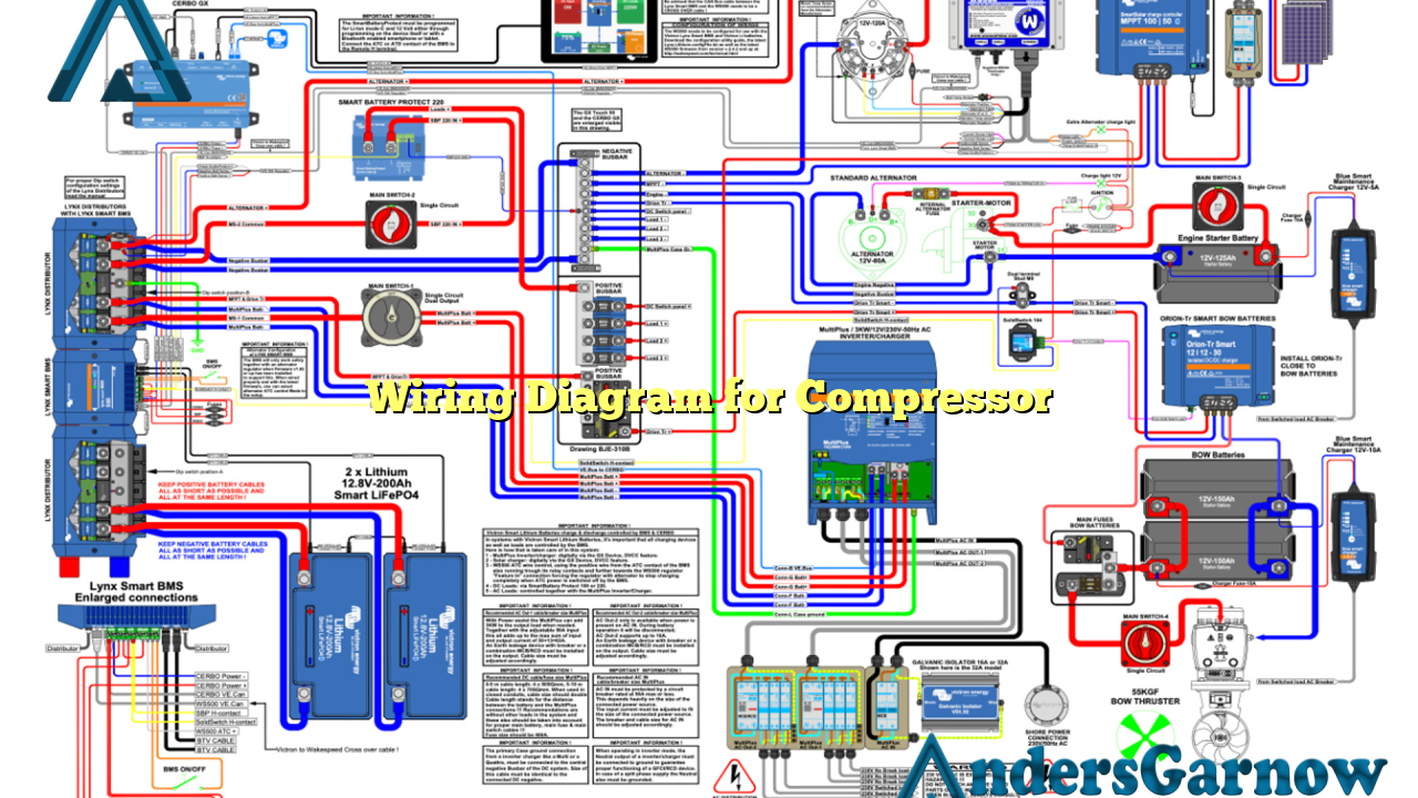
Before we dive into the details, it’s crucial to grasp the fundamental concepts of a wiring diagram for a compressor. This diagram showcases the various electrical components, such as the motor, capacitors, relays, and switches, and illustrates their interconnections. It serves as a guide for electricians and technicians to ensure the correct installation and maintenance of the compressor system.
Advantages:
- Provides a comprehensive overview of the electrical connections in the compressor system.
- Aids in troubleshooting electrical issues effectively.
- Assists in proper installation and prevents mistakes that may lead to system failure or accidents.
Disadvantages:
- Can be complex to understand for individuals without electrical knowledge.
- May require periodic updates to reflect any modifications or upgrades made to the system.
- Not suitable as a standalone guide; expertise in electrical work is still necessary.
2. Components of a Wiring Diagram
A wiring diagram for a compressor typically includes several key components:
| Component | Description |
|---|---|
| Motor | The main driving force behind the compressor’s functionality. |
| Capacitors | Store electrical energy to provide an extra boost during startup. |
| Relays | Act as switches to control the flow of electrical current. |
| Switches | Enable the user to turn the compressor on or off. |
| Power Supply | Provides the necessary electrical energy for the compressor to function. |
3. Creating a Wiring Diagram
To create an accurate wiring diagram for a compressor, follow these steps:
- Gather the necessary information about the compressor system, including its components and their specifications.
- Identify the power supply and ensure it meets the system requirements.
- Map out the interconnections between the components, considering the flow of electrical current.
- Label each component and connection point clearly for easy reference.
- Double-check the diagram for accuracy and make any necessary revisions.
4. Alternative Wiring Diagrams
While a traditional wiring diagram provides a comprehensive overview, there are alternative ways to represent the electrical connections. Some options include:
- Schematic Diagrams: Focuses on the electrical paths and connections without considering physical locations.
- Line Diagrams: Emphasizes the physical arrangement of components and their interconnections.
- Pictorial Diagrams: Utilizes visual representations of the components to aid in understanding.
5. Frequently Asked Questions (FAQ)
Q: Why is a wiring diagram essential for a compressor system?
A: A wiring diagram ensures proper installation, aids in troubleshooting, and prevents electrical mishaps.
Q: Can I create a wiring diagram without electrical expertise?
A: It is highly recommended to consult a qualified electrician or technician to ensure accuracy and safety.
Conclusion
In conclusion, a wiring diagram for a compressor is a crucial tool in understanding the electrical connections within the system. It provides a visual representation of the components, their interconnections, and aids in proper installation and troubleshooting. While it may seem complex to the untrained eye, consulting a professional is always recommended for accurate and safe implementation. So, make sure to utilize wiring diagrams when dealing with compressor systems to ensure optimal performance and longevity!
