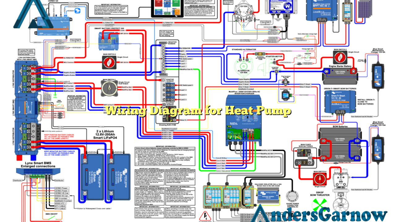
Hello readers, today we will discuss the wiring diagram for a heat pump. A heat pump is an essential component of any HVAC system, as it helps in both heating and cooling your home efficiently. Understanding the wiring diagram is crucial for proper installation and troubleshooting. In this article, we will break down the wiring diagram into 10 sub-sections and provide detailed explanations for each. So let’s dive in and explore the world of heat pump wiring!
1. The Basics of Heat Pump Wiring
The wiring diagram for a heat pump consists of various components such as the compressor, condenser, evaporator, reversing valve, fan motor, and thermostat. Each component has its own set of wires and connections. Understanding the basics of heat pump wiring is essential to ensure a successful installation and operation.
Advantages of Heat Pump Wiring
One of the significant advantages of heat pump wiring is its energy efficiency. Heat pumps consume less energy compared to traditional heating or cooling systems, resulting in lower utility bills. Additionally, heat pump wiring allows for both heating and cooling operations, making it a versatile choice for homeowners.
Disadvantages of Heat Pump Wiring
Despite its advantages, heat pump wiring has a few drawbacks. One of the main disadvantages is the initial cost of installation, which can be higher than traditional systems. Moreover, heat pumps may struggle to provide sufficient heating in extremely cold climates, requiring supplementary heating sources.
2. Understanding the Compressor Wiring
The compressor is the heart of a heat pump system. Its wiring diagram consists of various terminals such as common, start, and run. Each terminal serves a specific purpose in controlling the compressor’s operation. It is crucial to follow the manufacturer’s instructions and wiring diagram for proper installation and troubleshooting.
3. Exploring the Condenser Wiring
The condenser in a heat pump is responsible for releasing heat during the cooling process. Its wiring diagram includes terminals for power supply, fan motor, and capacitor. Understanding the condenser wiring is vital to ensure proper functioning and efficient cooling operation.
4. Decoding the Evaporator Wiring
The evaporator helps in absorbing heat from the surrounding air during the heating process. Its wiring diagram comprises terminals for power supply, fan motor, and defrost control. Proper understanding of the evaporator wiring is crucial for efficient heat absorption and distribution.
5. Reversing Valve Wiring
The reversing valve allows the heat pump to switch between heating and cooling modes. Its wiring diagram includes terminals for power supply and control inputs. Understanding the reversing valve wiring is essential for seamless mode transitions and optimal operation of the heat pump.
6. Fan Motor Wiring
The fan motor is responsible for circulating air within the HVAC system. Its wiring diagram includes terminals for power supply, speed control, and common connections. Proper fan motor wiring ensures efficient air circulation and enhances the overall performance of the heat pump.
7. Thermostat Wiring
The thermostat acts as the control center for the heat pump system. Its wiring diagram comprises terminals for power supply, heating and cooling outputs, and control inputs. Understanding the thermostat wiring is vital for accurate temperature control and efficient operation of the heat pump.
8. Alternative Wiring Diagrams
While the standard wiring diagram for a heat pump is widely used, there are alternative wiring options available. These alternatives may vary based on the specific model and brand of the heat pump. It is essential to consult the manufacturer’s documentation and follow the recommended wiring diagram for optimal performance.
9. Complete Wiring Diagram for Heat Pump
| Component | Terminals | Connections |
|---|---|---|
| Compressor | Common, Start, Run | Controlled by the thermostat |
| Condenser | Power supply, Fan motor, Capacitor | Controlled by the thermostat |
| Evaporator | Power supply, Fan motor, Defrost control | Controlled by the thermostat |
| Reversing Valve | Power supply, Control inputs | Controlled by the thermostat |
| Fan Motor | Power supply, Speed control, Common | Controlled by the thermostat |
| Thermostat | Power supply, Heating and cooling outputs, Control inputs | Controlled by the user |
10. Frequently Asked Questions (FAQ)
Q: Can I install a heat pump myself?
A: While it is possible to install a heat pump yourself, it is highly recommended to hire a professional HVAC technician. They have the required expertise and knowledge to ensure a safe and accurate installation.
Q: What is the lifespan of a heat pump?
A: The average lifespan of a heat pump is approximately 15 to 20 years. Proper maintenance and regular servicing can prolong its lifespan.
Q: Can a heat pump be used in extremely cold climates?
A: Heat pumps may struggle to provide sufficient heating in extremely cold climates. It is advisable to have a backup heating source in such conditions.
Conclusion
In conclusion, understanding the wiring diagram for a heat pump is essential for proper installation and troubleshooting. Each component, such as the compressor, condenser, evaporator, reversing valve, fan motor, and thermostat, has its own set of connections. By following the manufacturer’s instructions and utilizing the provided wiring diagram, you can ensure the efficient operation of your heat pump system. Remember to consult a professional HVAC technician for any installation or maintenance needs. Stay warm and cool with your well-wired heat pump!

