Hello readers,
In this article, we will discuss the topic of “wiring diagram for outlet” in detail. Understanding the wiring diagram for outlets is crucial for anyone involved in electrical work or even for homeowners who want to have a basic understanding of their electrical system. Whether you are an electrician, a DIY enthusiast, or a homeowner, this article will provide you with the necessary information to ensure the safe and efficient functioning of your outlets.
1. Introduction to Wiring Diagram for Outlet
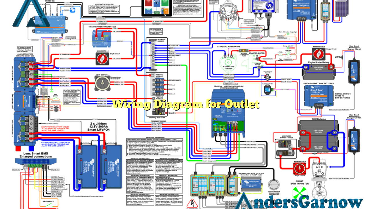
Before diving into the details, let’s first understand what a wiring diagram for an outlet is. A wiring diagram is a visual representation of the electrical circuitry of an outlet. It illustrates the connections between various components, such as the receptacle, the switch, and the wiring connections. By referring to a wiring diagram, electricians can ensure that the electrical connections are correct and troubleshoot any issues that may arise.
2. Components of a Wiring Diagram for Outlet
A wiring diagram for an outlet typically includes several components. These components include the receptacle, the switch, the hot wire, the neutral wire, and the ground wire. The receptacle is where you plug in your electrical devices, while the switch controls the flow of electricity to the outlet. The hot wire carries the current from the source to the outlet, the neutral wire completes the circuit, and the ground wire provides a safe path for excess electricity to flow in case of a fault.
3. Step-by-Step Guide for Wiring an Outlet
Now, let’s walk through the process of wiring an outlet using a wiring diagram:
- Turn off the power supply to the outlet by switching off the circuit breaker.
- Remove the cover plate of the existing outlet.
- Disconnect the wires from the old outlet, taking note of their positions.
- Connect the hot wire, neutral wire, and ground wire to the corresponding terminals of the new outlet.
- Secure the outlet in the electrical box using the provided screws.
- Attach the cover plate to the new outlet.
- Turn on the power supply and test the outlet using a voltage tester.
Following these steps and referring to a wiring diagram will ensure the correct installation of your outlet.
4. Advantages of Using a Wiring Diagram for Outlet
There are several advantages to using a wiring diagram for outlets:
- Accuracy: By following a wiring diagram, you can ensure that the connections are accurate, reducing the risk of electrical faults.
- Troubleshooting: If any issues arise with the outlet, a wiring diagram can help you identify and resolve them quickly.
- Consistency: Using a wiring diagram ensures consistency in electrical installations, making it easier for electricians to understand and work on the system.
5. Limitations of Using a Wiring Diagram for Outlet
While wiring diagrams are extremely helpful, they do have some limitations:
- Complexity: Wiring diagrams can be complex, especially for individuals with limited electrical knowledge. It is essential to have a basic understanding of electrical systems before attempting to interpret a wiring diagram.
- Specificity: Wiring diagrams are specific to the type of outlet and electrical system being used. It is crucial to ensure that you have the correct wiring diagram for your specific application.
6. Alternative Wiring Methods for Outlets
Aside from the traditional wiring diagram, there are alternative methods for wiring outlets:
- Daisy Chain Wiring: In this method, the outlets are connected in a series, with each outlet connecting to the next. This method is commonly used in residential settings.
- Split Circuit Wiring: Split circuit wiring allows for different electrical devices to be powered by different circuits originating from the same outlet box.
7. Wiring Diagram for Outlet – Quick Reference Table
| Component | Description |
|---|---|
| Receptacle | The outlet where electrical devices are plugged in. |
| Switch | Controls the flow of electricity to the outlet. |
| Hot Wire | Carries the current from the source to the outlet. |
| Neutral Wire | Completes the circuit and carries the return current. |
| Ground Wire | Provides a safe path for excess electricity to flow in case of a fault. |
8. Frequently Asked Questions (FAQ) – Wiring Diagram for Outlet
Q: Can I install an outlet without a wiring diagram?
A: While it is possible to install an outlet without a wiring diagram, it is highly recommended to use one to ensure the correct connections and avoid any potential electrical hazards.
Q: Are all outlets wired the same way?
A: No, outlets can be wired differently depending on the electrical system and the specific requirements of the installation. It is essential to refer to the appropriate wiring diagram for your situation.
Conclusion
In conclusion, understanding the wiring diagram for outlets is essential for safe and efficient electrical installations. By referring to a wiring diagram, you can accurately connect the various components of an outlet, troubleshoot issues, and ensure consistency in electrical work. Remember to follow the necessary safety precautions and consult a professional electrician if you are unsure about any aspect of your wiring project. Stay safe and enjoy your electrical projects!
