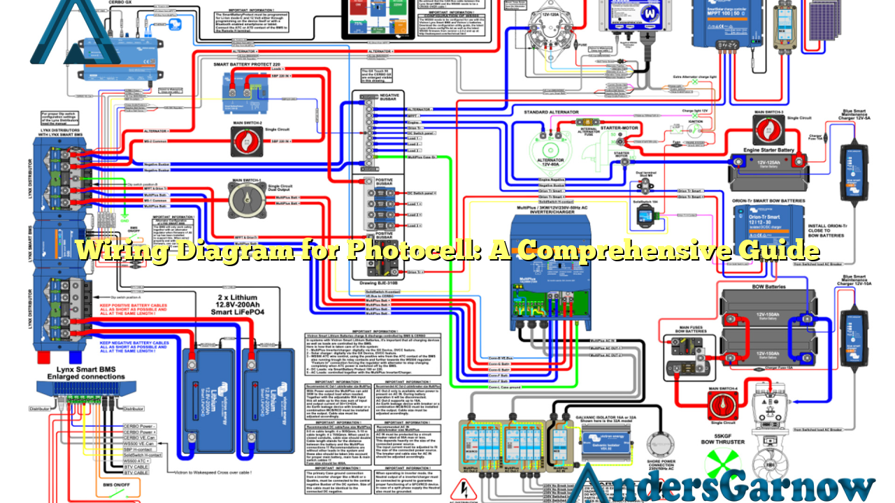
Hello there! In this article, we will delve into the intricate world of wiring diagrams for photocells. Whether you are a professional electrician or a DIY enthusiast, understanding how to properly install and wire a photocell is crucial. So, let’s explore the various aspects of wiring diagrams for photocells in detail.
1. Introduction to Photocells
Before we dive into the wiring diagrams, let’s first grasp the concept of photocells. Also known as photoelectric cells or light-dependent resistors (LDRs), photocells are devices that change their resistance based on the intensity of light falling on them. These devices are commonly used to control outdoor lighting, security systems, and automatic doors.
2. The Importance of Wiring Diagrams
Wiring diagrams play a vital role in ensuring the proper installation and functioning of photocells. They provide a visual representation of the electrical connections required for the photocell to operate efficiently. By following a wiring diagram, you can avoid potential errors and ensure a safe and reliable installation.
3. Wiring Diagram Components
A typical wiring diagram for a photocell consists of several components. These include the photocell itself, a power supply, a load (lighting fixture), and sometimes a control device such as a timer or a switch. Each component has a specific role in the circuit, and the wiring diagram illustrates how they are interconnected.
4. Wiring Diagram Symbols
Like any other electrical diagram, wiring diagrams for photocells also use specific symbols to represent different components and connections. Some common symbols you may encounter include lines, dots, circles, arrows, and various shapes. Understanding these symbols is crucial for interpreting the diagram accurately.
5. Wiring Diagram Types
There are two primary types of wiring diagrams for photocells: line diagrams and ladder diagrams. Line diagrams are simple and easy to understand, representing the circuit connections in a straight line format. On the other hand, ladder diagrams are more complex and commonly used in industrial settings.
6. Step-by-Step Wiring Process
Now, let’s walk through the step-by-step process of wiring a photocell. Firstly, ensure that the power supply is turned off to prevent any accidents. Then, follow the wiring diagram carefully, connecting the wires from the power supply, photocell, and load as indicated. Pay close attention to the polarity of the connections.
7. Advantages of Photocell Wiring
Using photocells for lighting control offers several advantages. Firstly, it enhances energy efficiency by automatically turning off lights during daylight hours. This feature not only reduces electricity consumption but also extends the lifespan of the lighting fixtures. Additionally, photocell wiring provides a convenient and automated way to control outdoor lighting, enhancing safety and security.
8. Limitations of Photocell Wiring
While photocell wiring has numerous benefits, it also has some limitations. One major limitation is the dependency on ambient light conditions. If the surrounding environment experiences constant changes in lighting intensity, the photocell may not function optimally. Additionally, photocells may require periodic maintenance and calibration to ensure accurate light detection.
9. Alternative Wiring Options
Aside from traditional photocell wiring, there are alternative options available. One such alternative is using motion sensors in conjunction with photocells. This hybrid approach combines the benefits of both technologies, allowing for more precise and efficient lighting control.
10. Wiring Diagram for Photocell – Complete Guide
To provide you with a comprehensive resource, we have created a detailed wiring diagram for photocells. The table below outlines all the necessary information, including wire colors, connection points, and component specifications.
| Wire Color | Connection Point | Component |
|---|---|---|
| Red | Power Supply Terminal 1 | Photocell |
| Black | Power Supply Terminal 2 | Photocell |
| White | Load Terminal 1 | Photocell |
| Blue | Load Terminal 2 | Photocell |
Conclusion
In conclusion, understanding wiring diagrams for photocells is essential for a successful installation and operation. By following the provided wiring diagram, you can ensure a safe and efficient connection of all components involved. Remember to consider the advantages and limitations of photocell wiring, and explore alternative options if necessary. Now, you are well-equipped to embark on your next photocell wiring project!

