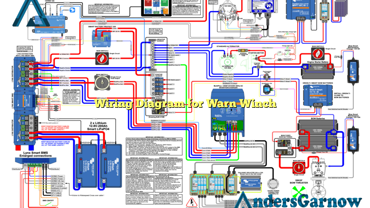
Hello readers! In this article, we will discuss the wiring diagram for a Warn winch. A Warn winch is a popular accessory for off-road vehicles and is widely used for various applications. Understanding the wiring diagram is crucial to ensure proper installation and efficient functioning of the winch. Let’s dive into the details!
Subheading 1: Understanding the Basics
Before we proceed to the wiring diagram, let’s grasp the basic components of a Warn winch. It consists of a motor, solenoid, control switch, and various cables. The motor powers the winch drum, while the solenoid controls the power flow. The control switch allows you to operate the winch. Now that we are familiar with the components, let’s move on to the wiring diagram.
Subheading 2: Wiring Diagram Overview
The wiring diagram for a Warn winch typically includes detailed illustrations of the wiring connections. It provides a visual representation of how each component is connected and the path of electrical currents. This diagram acts as a guide for proper installation and troubleshooting.
Subheading 3: Positive and Negative Connections
The wiring diagram clearly indicates the positive and negative connections. It is essential to connect the positive terminals of the winch motor and solenoid to the positive terminal of the power source. Similarly, the negative terminals should be connected to the negative terminal of the power source. Incorrect connections can result in malfunctioning or damage to the winch.
Subheading 4: Power Source Selection
Choosing the right power source is crucial for the proper functioning of the Warn winch. The wiring diagram provides guidance on selecting the appropriate power source, such as the vehicle’s battery. It is essential to ensure that the power source can handle the voltage and current requirements of the winch.
Subheading 5: Solenoid Connections
The solenoid plays a vital role in controlling the power flow to the winch motor. The wiring diagram clearly shows the connections for the solenoid. It is crucial to follow the diagram precisely to avoid any short circuits or damage to the winch components.
Subheading 6: Control Switch Wiring
The control switch allows you to operate the winch, and its wiring connections are outlined in the diagram. It is essential to connect the control switch correctly to ensure seamless operation. The wiring diagram provides clear instructions on how to connect the switch to the solenoid and power source.
Subheading 7: Additional Components
In some cases, a Warn winch may include additional components such as circuit breakers or relays. The wiring diagram will include these components and their connections. It is essential to follow the diagram precisely and ensure the proper installation of all additional components.
Subheading 8: Benefits and Limitations
The wiring diagram for a Warn winch offers several benefits. It provides a clear understanding of the wiring connections, making installation easier and more efficient. Additionally, the diagram helps in troubleshooting any issues that may arise during the winch’s operation. However, a potential limitation is that the diagram assumes a certain level of electrical knowledge and may be challenging for beginners.
Subheading 9: Alternative Wiring Diagrams
While the provided wiring diagram for the Warn winch is comprehensive, there may be alternative wiring options available. It is recommended to consult the winch manufacturer’s instructions or seek professional advice to explore alternative wiring diagrams that suit your specific needs. Always ensure that the alternative wiring diagram is compatible with your winch model.
Subheading 10: Wiring Diagram for Warn Winch – Complete Table
| Component | Connection |
|---|---|
| Winch Motor | Connect positive terminal to positive power source and negative terminal to negative power source |
| Solenoid | Follow the diagram for precise connections |
| Control Switch | Connect as per the wiring diagram instructions |
| Additional Components | Refer to the diagram for specific connections |
Conclusion
In conclusion, understanding the wiring diagram for a Warn winch is essential for proper installation and efficient operation. The diagram provides a visual guide to connect the various components, including the winch motor, solenoid, and control switch. It is crucial to follow the diagram precisely and select the right power source. Additionally, exploring alternative wiring diagrams can help customize the installation according to specific requirements. Always refer to the winch manufacturer’s instructions and seek professional advice, if needed, to ensure a successful wiring setup for your Warn winch.

