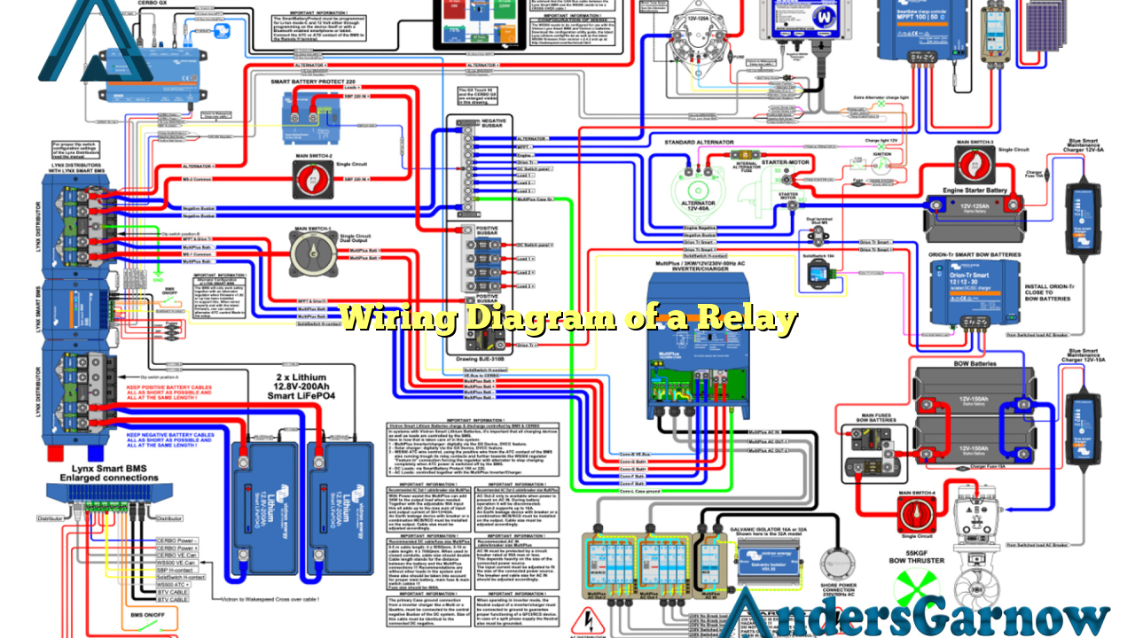
Hello there! In this article, we will explore the fascinating world of relay wiring diagrams. Relays play a crucial role in various electrical systems, and understanding their wiring diagrams is essential for anyone working with electrical circuits. So, let’s dive in and unravel the mysteries of relay diagrams!
1. Introduction to Relays
Relays are electrically operated switches that control the flow of current in a circuit. They consist of an electromagnetic coil and a set of contacts. When the coil is energized, it creates a magnetic field that attracts or repels the contacts, thus opening or closing the circuit.
2. The Purpose of Relay Wiring Diagrams
Relay wiring diagrams provide a visual representation of how the various components in a relay circuit are connected. They help technicians and engineers understand the circuit’s functionality, troubleshoot any issues, and ensure proper installation.
3. Components of a Relay Wiring Diagram
A typical relay wiring diagram consists of several components, including:
| Component | Description |
|---|---|
| Coil | The electromagnetic coil that generates the magnetic field. |
| Contacts | The moving parts of the relay that open or close the circuit. |
| Control Circuit | The portion of the circuit that controls the relay. |
| Load Circuit | The portion of the circuit that is controlled by the relay. |
4. Understanding Relay Symbols
Relay wiring diagrams use various symbols to represent different components and connections. Some commonly used symbols include:
– Coil: represented by a zigzag line
– Normally Open (NO) Contact: represented by a line with a gap
– Normally Closed (NC) Contact: represented by a solid line
– Common (COM) Contact: represented by a line connected to both NO and NC contacts
5. Wiring a Relay for a Simple Circuit
Let’s take a look at wiring a relay for a simple circuit. In this example, we will use a 5V relay to control the operation of a lamp. The wiring diagram would consist of a power source connected to the coil, contacts connected to the lamp and power source, and control switches connected to the coil.
Advantages of a Relay Wiring Diagram:
– Provides a clear understanding of the circuit connections
– Helps diagnose and troubleshoot issues easily
– Ensures proper installation and prevents wiring mistakes
Disadvantages of a Relay Wiring Diagram:
– Can be complex for beginners to understand
– Requires accurate interpretation of symbols and connections
6. Alternative Wiring Methods for Relays
While relay wiring diagrams are commonly used, there are alternative methods for wiring relays, such as ladder diagrams and schematics. These methods offer different visual representations of circuits and may be preferred in specific industries or applications.
7. Frequently Asked Questions (FAQ)
Q: Can I use a relay to control high voltage circuits?
A: Yes, relays are commonly used to control high voltage circuits. However, it is crucial to ensure that the relay’s specifications and ratings match the requirements of the circuit.
Q: How do I determine the appropriate relay for my circuit?
A: To choose the right relay, consider factors such as the voltage and current requirements of the circuit, the switching speed needed, and any special features required (such as latching or time delay).
In Conclusion
In conclusion, understanding the wiring diagram of a relay is essential for anyone working with electrical circuits. These diagrams provide a visual representation of how relays are wired and help ensure the proper functioning of electrical systems. Whether you are a technician, engineer, or enthusiast, mastering relay wiring diagrams will greatly enhance your ability to work with electrical circuits.

