Hello and welcome to our article on wiring diagram solenoid. In this comprehensive guide, we will provide you with detailed information about wiring diagrams for solenoids, their advantages, disadvantages, and alternative options. So, let’s dive right in!
1. Understanding Solenoids
Before we delve into the wiring diagram, let’s first understand what a solenoid is. A solenoid is an electrical component that converts electrical energy into mechanical movement. It consists of a coil of wire wrapped around a metal core. When an electric current passes through the coil, a magnetic field is created, causing the core to move, either attracting or repelling other metal objects.
2. Wiring Diagram for Solenoid
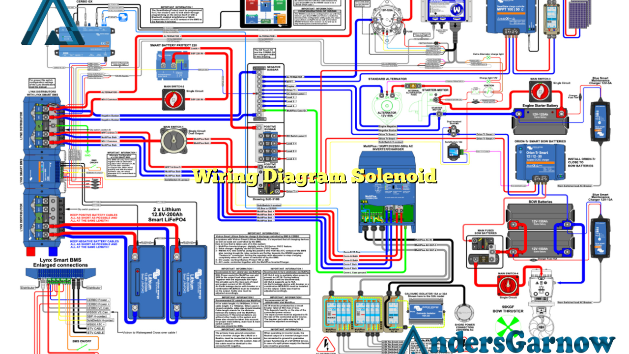
The wiring diagram for a solenoid typically includes the connection of the power source, the solenoid coil, and any additional components such as switches or relays. It is essential to follow the specific wiring diagram provided by the manufacturer to ensure proper functioning and safety.
Advantages of Wiring Diagram Solenoid:
1. Simplicity: Wiring diagram solenoids are relatively simple to understand and implement. The diagrams provide clear instructions on how to connect the various components, making installation and troubleshooting easier.
2. Efficiency: Solenoids are highly efficient devices that convert electrical energy into mechanical motion with minimal energy loss. This efficiency makes them ideal for various applications, including automotive, industrial, and home automation systems.
Disadvantages of Wiring Diagram Solenoid:
1. Limited Range: Solenoids have a limited range of motion and can only produce linear movement. If rotational or complex movements are required, additional mechanisms or components may be necessary.
2. Power Consumption: While solenoids are efficient in converting energy, they still consume electrical power. In applications where power consumption is a concern, alternative solutions might be more suitable.
3. Alternative Options
There are alternative options available for controlling mechanical movement besides solenoids. One popular alternative is the use of stepper motors. Stepper motors provide precise control over rotational movement and can be easily integrated into various systems.
Another alternative is the use of servo motors. Servo motors offer high torque and precise positioning capabilities, making them suitable for applications that require accurate control over movement.
4. Wiring Diagram Solenoid Table
| Component | Connection |
|---|---|
| Power Source | Connect the positive terminal of the power source to one end of the solenoid coil and the negative terminal to the other end. |
| Switch/Relay | Connect the switch or relay between the power source and the solenoid coil to control the flow of current. |
5. Frequently Asked Questions (FAQ)
Q: Can I use a solenoid for continuous operation?
A: Solenoids are typically designed for intermittent operation due to heat buildup during continuous use. If continuous operation is required, it is recommended to use a solenoid with proper cooling mechanisms or consider alternative options.
Q: Can I use a different power source voltage for the solenoid?
A: It is crucial to use the specified voltage mentioned in the solenoid’s datasheet or manual. Using a different voltage may result in improper operation or even damage to the solenoid.
Conclusion
In conclusion, understanding the wiring diagram for solenoids is crucial for proper installation and operation. Solenoids offer simplicity and efficiency but have limitations in terms of range and power consumption. Considering alternative options such as stepper motors or servo motors may be beneficial depending on the specific application requirements. Always refer to the manufacturer’s instructions and specifications for accurate wiring and usage guidelines.
