Hello and welcome to our detailed guide on wiring relay diagrams. In this article, we will explore everything you need to know about wiring relay diagrams, their advantages and disadvantages, and alternative options. Whether you are an experienced electrician or a DIY enthusiast, understanding wiring relay diagrams is crucial for efficient and reliable electrical installations.
1. What is a Wiring Relay Diagram?
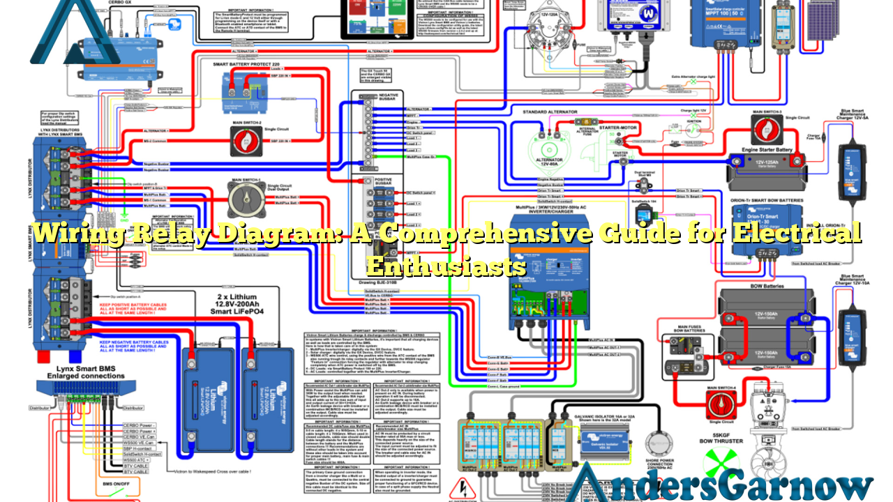
A wiring relay diagram is a visual representation of the electrical connections and circuitry for controlling various devices using relays. Relays are electromechanical switches that use a small control signal to activate a larger current or voltage. These diagrams provide a clear overview of how the electrical system is wired, enabling easy troubleshooting and installation.
2. Understanding the Components
Before diving into the diagram itself, let’s familiarize ourselves with the key components involved in a typical wiring relay diagram:
| Component | Description |
|---|---|
| Relay | An electromechanical switch used to control the flow of current or voltage. |
| Coil | The part of the relay that generates the magnetic field when the control signal is applied. |
| Contact | The part of the relay that opens or closes the circuit based on the relay’s state. |
| Control Signal | A small electrical signal that activates the relay. |
| Power Source | The electrical supply that energizes the relay and the devices it controls. |
| Load | The device or equipment controlled by the relay. |
3. Advantages of Wiring Relay Diagrams
Using wiring relay diagrams provides several benefits:
- Clear Visualization: Wiring relay diagrams offer a clear and concise visual representation of complex electrical connections, making it easier to understand and troubleshoot.
- Efficient Troubleshooting: When an electrical issue arises, a wiring relay diagram helps identify the exact location of the problem, saving time and effort in troubleshooting.
- Enhanced Safety: By understanding the wiring relay diagram, electricians can ensure proper isolation of circuits during maintenance or repairs, reducing the risk of electrical accidents.
- Optimized Installations: These diagrams help plan and execute efficient electrical installations, minimizing errors and ensuring reliable operation.
4. Disadvantages of Wiring Relay Diagrams
While wiring relay diagrams are incredibly useful, they do have some limitations:
- Complexity: Some wiring relay diagrams can be complex, especially in large-scale systems, requiring a thorough understanding of electrical circuitry.
- Updates and Modifications: When modifications or updates are made to the electrical system, the wiring relay diagram may need to be revised, adding extra effort and time.
- Dependency on Accuracy: Any inaccuracies or errors in the diagram can lead to faulty installations or troubleshooting, emphasizing the need for precise documentation.
5. Exploring Alternative Options
While wiring relay diagrams are commonly used, there are alternative options available for controlling electrical devices:
- Programmable Logic Controllers (PLCs): PLCs offer advanced control capabilities and can replace wiring relay diagrams in complex automation systems.
- Microcontrollers: Microcontrollers provide a cost-effective solution for controlling devices in small-scale applications and projects.
- Smart Home Systems: With the rise of smart home technology, wireless control systems using smartphones or voice commands are becoming popular alternatives.
Conclusion
In conclusion, wiring relay diagrams are essential tools for electrical enthusiasts. They provide a comprehensive overview of electrical connections and facilitate efficient troubleshooting and installation processes. While they have their limitations, the advantages of using wiring relay diagrams outweigh the disadvantages. By understanding the components, advantages, disadvantages, and alternative options, you can make informed decisions when working with electrical systems.
Frequently Asked Questions (FAQ)
1. What is the purpose of a wiring relay diagram?
A wiring relay diagram helps electricians and DIY enthusiasts understand the electrical connections and circuitry for controlling devices using relays. It provides a visual representation of the system, aiding in troubleshooting and installation processes.
2. Are wiring relay diagrams only used in large-scale systems?
No, wiring relay diagrams are used in both small-scale and large-scale systems. They are particularly useful in systems where multiple devices need to be controlled, regardless of the system’s size.
3. Can I modify a wiring relay diagram?
Yes, wiring relay diagrams can be modified to accommodate changes or updates in the electrical system. However, it is crucial to ensure accuracy and document any modifications for future reference.
4. Are there any alternatives to wiring relay diagrams?
Yes, alternatives to wiring relay diagrams include programmable logic controllers (PLCs), microcontrollers, and smart home systems. These alternatives offer advanced control capabilities and wireless control options.
5. Do I need to be an expert electrician to understand wiring relay diagrams?
While a basic understanding of electrical circuitry is beneficial, wiring relay diagrams are designed to be user-friendly and accessible to both experienced electricians and DIY enthusiasts. With the right resources and knowledge, anyone can comprehend and utilize these diagrams effectively.
