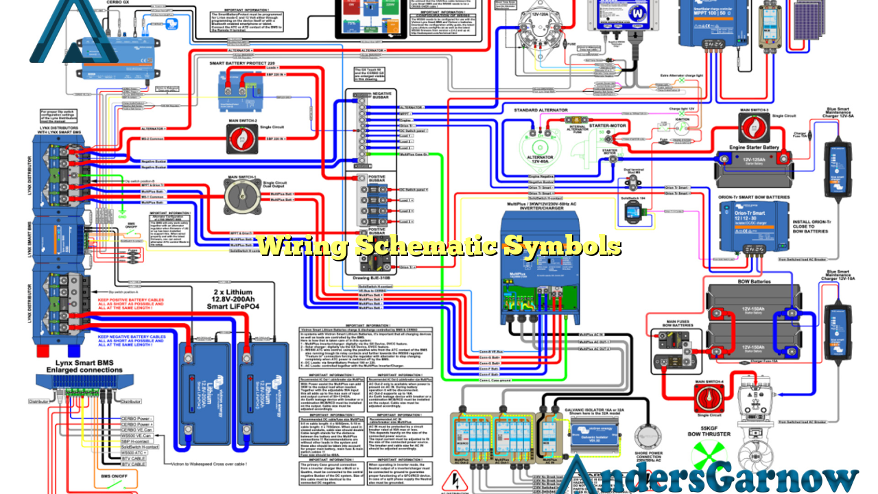
Hello readers! In this article, we will delve into the world of wiring schematic symbols. These symbols are essential for understanding electrical diagrams and blueprints and play a crucial role in the field of electrical engineering. So, let’s explore the key aspects of wiring schematic symbols in detail.
1. Understanding the Importance of Wiring Schematic Symbols
Wiring schematic symbols serve as a universal language for electrical engineers and technicians. These symbols provide a visual representation of various electrical components and their connections in a circuit. By using these symbols, professionals can easily interpret and analyze complex wiring diagrams, making troubleshooting and designing electrical systems more efficient.
Advantages of Wiring Schematic Symbols:
- Standardization: Wiring schematic symbols are standardized, ensuring consistency and ease of communication across different industries and regions.
- Clarity: These symbols provide a clear and concise representation of complex electrical concepts, making it easier for professionals to understand and work with.
- Efficiency: By using symbols, engineers can quickly identify components and connections, saving time and effort in the design and troubleshooting processes.
- Accuracy: Wiring schematic symbols help eliminate errors and misunderstandings that may occur when using textual descriptions alone.
Disadvantages of Wiring Schematic Symbols:
- Learning Curve: Understanding and memorizing the various symbols can be challenging, especially for beginners in the field of electrical engineering.
- Complexity: Some electrical diagrams can become highly intricate, requiring a deep understanding of multiple symbols and their combinations.
- Updates: With advancements in technology, new components and symbols are introduced, necessitating continuous learning and adaptation.
2. Common Wiring Schematic Symbols
To effectively read and interpret electrical diagrams, one must be familiar with the most commonly used wiring schematic symbols. Here are some key symbols:
| Symbol | Description |
|---|---|
| Resistor | A component that resists the flow of electric current |
| Capacitor | A device that stores and releases electrical energy |
| Inductor | A coil that generates a magnetic field when current passes through it |
| Diode | A semiconductor device that allows current to flow in one direction |
| Transistor | An electronic switch or amplifier |
| Ground | A connection to the Earth, used as a reference point |
| Battery | A device that provides a source of electrical energy |
| Switch | A device used to interrupt or divert the flow of current |
| Fuse | A safety device that breaks the circuit when excessive current flows through it |
| Transformer | A device that transfers electrical energy between circuits through electromagnetic induction |
3. Alternative Approaches to Wiring Schematic Symbols
While wiring schematic symbols are widely used and accepted, alternative approaches exist for representing electrical components and connections. One such approach is the use of color codes and labels instead of symbols. This method is commonly employed in industries where space is limited or for quick reference purposes. However, it is important to note that wiring schematic symbols remain the industry standard due to their effectiveness and widespread adoption.
4. Frequently Asked Questions (FAQ) about Wiring Schematic Symbols
Q: How can I learn and memorize wiring schematic symbols effectively?
A: Practice is key! Start by familiarizing yourself with the most commonly used symbols and gradually expand your knowledge. Utilize online resources, textbooks, and hands-on projects to reinforce your understanding.
Q: Are wiring schematic symbols the same worldwide?
A: While the basic symbols remain consistent, slight variations may exist between different countries or industries. It is essential to refer to the specific standards and guidelines applicable to your region.
Q: Can I create my own wiring schematic symbols?
A: Yes, in certain cases, custom symbols may be used to represent unique components or connections. However, it is crucial to ensure proper documentation and communication to avoid confusion.
Conclusion
In conclusion, wiring schematic symbols are vital tools for electrical engineers and technicians. They provide a standardized and efficient means of representing electrical components and connections in diagrams and blueprints. While there may be a learning curve associated with these symbols, their benefits far outweigh the challenges. By familiarizing oneself with the common symbols and their meanings, professionals can effectively design, troubleshoot, and communicate electrical systems.
