Hello readers, welcome to our in-depth article on wiring schematics. In this comprehensive guide, we will delve into the world of electrical connections, exploring their intricacies, advantages, disadvantages, and alternative options. Whether you are a professional electrician or a curious homeowner, this article will provide you with valuable insights into understanding wiring schematics and their role in electrical systems.
1. Introduction to Wiring Schematics
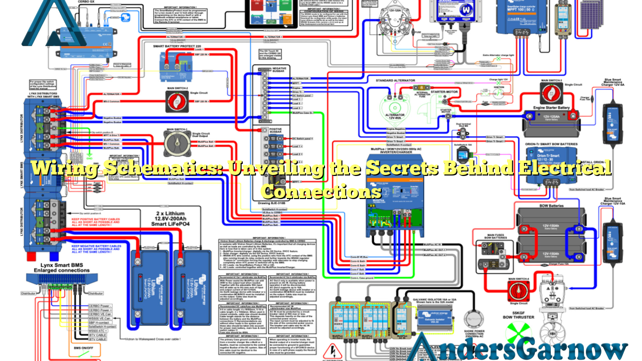
Wiring schematics, also known as electrical diagrams or circuit diagrams, serve as visual representations of electrical connections within a system. These intricate drawings illustrate the arrangement of wires, components, and their connections, enabling electricians and engineers to analyze, troubleshoot, and design electrical circuits.
Advantages of Wiring Schematics
One of the key advantages of wiring schematics is their ability to provide a clear and concise overview of complex electrical systems. By following the lines, symbols, and notations, professionals can quickly understand the connections, voltage ratings, and functionality of various components.
Additionally, wiring schematics aid in the identification of potential issues within a circuit. Whether it’s a short circuit, open connection, or incorrect wiring, these diagrams enable electricians to pinpoint the problem area and rectify it efficiently.
Disadvantages of Wiring Schematics
Despite their numerous advantages, wiring schematics do have some limitations. One of the main drawbacks is their complexity, especially for individuals without a strong background in electrical engineering. The intricate symbols and technical notations can be overwhelming for beginners, making it challenging to interpret the diagrams accurately.
Furthermore, wiring schematics may not always reflect the actual physical layout of the components. While the connections and functionality are accurately represented, the physical positioning of wires and components may differ, leading to potential confusion during installation or repair.
2. Understanding Wiring Symbols
Wiring schematics utilize a standardized set of symbols to represent different electrical components and their connections. These symbols help electricians and engineers quickly identify the various elements within a circuit.
For instance, a straight line typically represents a wire, while a circle denotes a junction or connection point. Other symbols include resistor (zigzag line), capacitor (parallel plates), and switch (open/close). Familiarizing yourself with these symbols is crucial for comprehending wiring schematics.
3. Types of Wiring Schematics
There are different types of wiring schematics, each serving a specific purpose. The most common types include:
- Single Line Diagrams (SLDs): SLDs are simplified diagrams that show the electrical connections between major components in a system. They provide an overview of the power flow and are commonly used in large-scale projects.
- Wiring Diagrams: Wiring diagrams focus on the physical layout of wires and components. They are often used during installation or repair and provide a detailed representation of the circuit’s physical arrangement.
- Schematic Diagrams: Schematic diagrams offer a comprehensive view of the electrical connections, including details about wire sizes, colors, and connections to specific terminals. They are commonly used in industrial applications.
4. Benefits of Using Wiring Schematics
Using wiring schematics offers several benefits, including:
- Accuracy: Wiring schematics ensure accurate electrical connections, reducing the chances of errors during installation or repair.
- Troubleshooting: When issues arise, wiring schematics serve as invaluable tools for diagnosing and rectifying problems efficiently.
- Design and Planning: Wiring schematics aid in the design and planning stages of electrical systems, ensuring optimal performance and safety.
5. Alternative Options to Wiring Schematics
While wiring schematics are widely used and highly effective, alternative options exist for specific applications. Some alternatives include:
- Block Diagrams: Block diagrams provide an overview of a system’s components and their interconnections, focusing on functionality rather than the specific wiring details.
- Logic Diagrams: Logic diagrams are used in digital circuits to illustrate the flow of signals and logic gates, enabling engineers to analyze and design complex digital systems.
- Pictorial Diagrams: Pictorial diagrams use realistic images of components instead of symbols, making them more accessible to individuals with limited technical knowledge.
6. Wiring Schematics Table
| Component | Symbol | Description |
|---|---|---|
| Wire |  Source: None Source: None |
A conductor used to carry electrical current. |
| Resistor |  Source: None Source: None |
A component that limits the flow of current in a circuit. |
| Capacitor |  Source: None Source: None |
A device that stores electrical energy in an electric field. |
| Switch |  Source: None Source: None |
A device used to interrupt or divert the flow of current. |
7. Frequently Asked Questions (FAQ)
Q: Are wiring schematics universally standardized?
A: While there are standard symbols used in wiring schematics, variations can exist based on regional or industry-specific conventions. It is essential to familiarize yourself with the specific standards used in your area.
Q: Can I create my own wiring schematics?
A: Yes, with the proper knowledge and tools, you can create wiring schematics for your electrical projects. However, it is crucial to ensure accuracy and adhere to recognized standards to avoid any potential issues.
Q: Where can I find wiring schematics for specific appliances?
A: Many manufacturers provide wiring schematics in the user manuals or on their official websites. You can also consult professional electricians or online resources dedicated to electrical diagrams.
Conclusion
In conclusion, wiring schematics play a vital role in the world of electrical connections. Their ability to provide a visual representation of complex circuits enables professionals to design, troubleshoot, and repair electrical systems efficiently. While they may be challenging for beginners, understanding the symbols and conventions used in wiring schematics is a valuable skill for anyone involved in electrical work. So, embrace the power of wiring schematics and unlock the secrets behind electrical connections!
