Hello and welcome to our article on compressor wiring diagram. In this guide, we will provide you with a detailed overview of compressor wiring diagrams, including their benefits, drawbacks, and alternative options. Whether you are an HVAC technician or a DIY enthusiast, understanding compressor wiring diagrams is essential for troubleshooting and maintaining your compressor effectively.
1. Understanding the Basics of Compressor Wiring Diagram
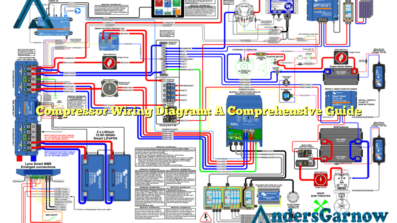
Compressor wiring diagrams are schematic representations of the electrical connections and components within a compressor system. These diagrams provide a visual guide for understanding how to properly wire the compressor motor, capacitors, relays, and other essential components.
By referring to a compressor wiring diagram, you can easily identify the correct wiring connections, voltages, and phase requirements for your specific compressor model. This ensures safe and efficient operation of the compressor, preventing any potential damage or malfunction.
2. The Benefits of Compressor Wiring Diagram
Compressor wiring diagrams offer several advantages. Firstly, they provide a clear and concise visual representation of the electrical connections, making it easier to understand and follow the wiring process. This is particularly useful for individuals who are new to compressor systems or electrical wiring.
Secondly, compressor wiring diagrams help in troubleshooting electrical issues. By referring to the diagram, you can quickly identify any incorrect wiring connections or faulty components, allowing you to rectify the problem promptly. This saves time and effort in diagnosing and resolving electrical faults.
Lastly, compressor wiring diagrams ensure compliance with safety standards. Following the correct wiring procedures outlined in the diagram reduces the risk of electrical shock or fire hazards, promoting a safe working environment.
3. Drawbacks of Compressor Wiring Diagram
While compressor wiring diagrams are highly beneficial, there are a few drawbacks to consider. One limitation is that these diagrams can vary depending on the compressor manufacturer and model. Therefore, it is crucial to obtain the correct wiring diagram specific to your compressor to ensure accuracy.
Additionally, some compressor wiring diagrams may be complex and difficult to interpret, especially for individuals with limited electrical knowledge. In such cases, it is advisable to seek professional assistance or consult the manufacturer’s documentation for further guidance.
4. Exploring Alternative Options
Aside from traditional compressor wiring diagrams, there are alternative options available for wiring compressor systems. One popular alternative is the use of plug-and-play wiring harnesses. These harnesses simplify the wiring process by providing pre-wired connections that can be easily plugged into the compressor components.
Plug-and-play wiring harnesses are particularly beneficial for individuals who are not familiar with electrical wiring or those who prefer a more straightforward installation process. They eliminate the need to decipher complex wiring diagrams and ensure correct connections with minimal effort.
5. Compressor Wiring Diagram: A Step-by-Step Guide
To help you better understand compressor wiring diagrams, we have provided a step-by-step guide below:
| Step | Description |
|---|---|
| Step 1 | Gather the necessary tools and equipment, including the compressor wiring diagram, wire strippers, electrical tape, and a screwdriver. |
| Step 2 | Ensure that the power supply to the compressor is turned off to prevent any electrical accidents. |
| Step 3 | Refer to the wiring diagram and identify the different components, such as the compressor motor, capacitors, and relays. |
| Step 4 | Strip the insulation from the wires according to the diagram’s instructions. |
| Step 5 | Connect the wires to their respective terminals as shown in the diagram, ensuring proper color-coding and tight connections. |
| Step 6 | Use electrical tape to secure and insulate the connections to prevent any short circuits or exposed wires. |
| Step 7 | Double-check all the connections against the diagram to ensure accuracy. |
| Step 8 | Turn on the power supply and test the compressor to verify its proper functioning. |
Conclusion
In conclusion, a compressor wiring diagram is an essential tool for understanding and correctly wiring a compressor system. While they have some limitations, the benefits of using wiring diagrams outweigh the drawbacks. They provide a visual guide, aid in troubleshooting, and ensure compliance with safety standards.
Remember to always refer to the specific wiring diagram for your compressor model and consider alternative options such as plug-and-play wiring harnesses. By following the correct wiring procedures, you can ensure the efficient and safe operation of your compressor system.
Frequently Asked Questions (FAQ)
Q: Where can I find the wiring diagram for my compressor model?
A: The wiring diagram can usually be found in the compressor’s user manual or on the manufacturer’s website. If you are unable to locate it, consider contacting the manufacturer directly for assistance.
Q: Can I use a generic wiring diagram for my compressor?
A: It is highly recommended to use the specific wiring diagram provided by the compressor manufacturer. Generic wiring diagrams may not accurately represent the electrical connections and specifications of your compressor model.
Q: What should I do if I encounter difficulties while wiring my compressor?
A: If you are unsure or encounter difficulties during the wiring process, it is best to seek professional help from a qualified HVAC technician or an electrician. They have the expertise and knowledge to ensure proper wiring and troubleshoot any issues effectively.
