Hello readers! In this article, we will explore the world of contact wiring diagrams. Whether you are an electrical engineer, a technician, or simply someone interested in understanding the intricacies of electrical systems, this guide will provide you with valuable insights into contact wiring diagrams and their importance in various applications.
1. Understanding Contact Wiring Diagrams
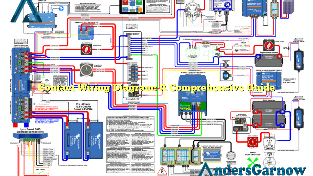
Contact wiring diagrams are graphical representations of electrical circuits that depict the connections between different components, such as switches, relays, and motors. These diagrams use standardized symbols to illustrate the flow of current and provide a visual representation of how a circuit is wired.
One of the key advantages of contact wiring diagrams is that they enable technicians and engineers to understand the electrical connections within a system without physically inspecting the components. This makes troubleshooting and maintenance tasks much more efficient and reduces the risk of errors.
However, contact wiring diagrams can be complex, especially for large-scale systems. It requires a good understanding of electrical principles and the ability to interpret symbols accurately. Additionally, any errors or inaccuracies in the diagram can lead to serious consequences, such as malfunctioning equipment or electrical hazards.
2. Benefits of Contact Wiring Diagrams
Contact wiring diagrams offer several benefits in various industries and applications:
| Benefits | Explanation |
|---|---|
| Clear Visualization | They provide a clear and concise visual representation of complex electrical circuits. |
| Troubleshooting Aid | They assist technicians in identifying and resolving electrical faults quickly. |
| Standardization | They follow standardized symbols and conventions, ensuring consistency and ease of understanding. |
| Documentation | They serve as valuable documentation for future reference and system upgrades. |
These benefits highlight the importance of contact wiring diagrams in ensuring efficient and safe electrical operations.
3. Common Symbols Used in Contact Wiring Diagrams
Contact wiring diagrams use specific symbols to represent different electrical components. Here are some commonly used symbols:
– Switches: Represented by various shapes, such as circles or rectangles, with or without arrows to indicate the type of switch.
– Relays: Depicted as square boxes with control and power terminals.
– Motors: Shown as circles with the motor type indicated inside.
– Connectors: Denoted by dots or lines joining different components.
These symbols form the building blocks of contact wiring diagrams and enable engineers and technicians to understand the circuit connections at a glance.
4. How to Read a Contact Wiring Diagram
Reading a contact wiring diagram involves understanding the symbols and their meanings, as well as the flow of current through the circuit. Here are the general steps to read a contact wiring diagram:
1. Familiarize yourself with the symbols used in the diagram.
2. Identify the power source and the direction of current flow.
3. Follow the lines and connections to trace the path of current through the circuit.
4. Analyze the switches, relays, and other components to understand their roles in the circuit.
5. Interpret any additional labels or annotations provided in the diagram.
By following these steps, you can gain a comprehensive understanding of the circuit connections and identify any potential issues or improvements.
5. Common Mistakes and Challenges in Contact Wiring Diagrams
While contact wiring diagrams are immensely useful, they are not without their challenges. Here are some common mistakes and challenges encountered:
– Inaccurate or outdated diagrams: Over time, modifications or upgrades to electrical systems may render the existing diagrams inaccurate or outdated. It is essential to ensure that the diagrams are regularly updated to reflect the current state of the system.
– Lack of standardization: In some cases, different manufacturers or industries may use their own set of symbols or conventions, leading to confusion and misinterpretation. It is crucial to establish standardized practices to overcome this challenge.
– Complex systems: Large-scale electrical systems can be extremely complex, making it challenging to create accurate and easily understandable contact wiring diagrams. Proper documentation, labeling, and organization are key to addressing this challenge.
By being aware of these potential pitfalls, engineers and technicians can take the necessary precautions to ensure the accuracy and reliability of contact wiring diagrams.
6. Alternative Approaches to Contact Wiring Diagrams
While contact wiring diagrams are widely used, alternative approaches have emerged to simplify the understanding and design of electrical circuits. One such approach is the use of computer-aided design (CAD) software.
CAD software allows engineers to create digital representations of electrical circuits, complete with interactive features and real-time simulations. This enables easier visualization, analysis, and modification of circuits, reducing the reliance on traditional paper-based contact wiring diagrams.
However, it is important to note that CAD software should be used in conjunction with standardized symbols and conventions to ensure consistency and compatibility across different systems and industries.
Conclusion
In conclusion, contact wiring diagrams are vital tools for understanding, designing, and maintaining electrical systems. They provide a visual representation of complex circuits, assist in troubleshooting, and ensure standardized practices. While they can be challenging to create and interpret accurately, their benefits outweigh the potential pitfalls. By adhering to standardized symbols, regularly updating diagrams, and utilizing alternative approaches such as CAD software, engineers and technicians can harness the power of contact wiring diagrams to ensure the safe and efficient operation of electrical systems.
Frequently Asked Questions (FAQ)
Q: Can I rely solely on contact wiring diagrams for troubleshooting electrical faults?
A: While contact wiring diagrams are valuable aids in troubleshooting, other diagnostic tools and techniques may be necessary, such as multimeters, circuit testers, or oscilloscopes.
Q: How often should contact wiring diagrams be updated?
A: Contact wiring diagrams should be updated whenever modifications or upgrades are made to the electrical system. Regular reviews and updates are essential to maintain accuracy.
Q: Are contact wiring diagrams universal across different industries?
A: While contact wiring diagrams follow standardized symbols and conventions, there may be slight variations or industry-specific practices. It is important to ensure compatibility and understanding across different industries.
Q: Can CAD software completely replace traditional contact wiring diagrams?
A: CAD software provides additional features and flexibility in designing and analyzing electrical circuits. However, traditional contact wiring diagrams still serve as important documentation and reference material.
