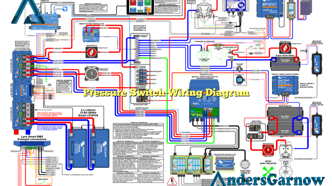
Hello readers! In this article, we will discuss the pressure switch wiring diagram in detail. A pressure switch is an essential component in many industrial and residential applications. It is used to monitor and control the pressure of a system, ensuring safe and efficient operation. Understanding how to properly wire a pressure switch is crucial for its correct functioning. So, let’s dive into the world of pressure switch wiring diagrams!
1. What is a Pressure Switch?
A pressure switch is a device that senses changes in pressure and reacts accordingly. It consists of a sensing element, usually a diaphragm or a bellows, and electrical contacts. When the pressure reaches a certain threshold, the contacts either open or close, triggering an action in the system. This action can be turning on or off a motor, activating an alarm, or controlling a valve.
2. Types of Pressure Switches
There are various types of pressure switches available, including electromechanical, solid-state, and differential pressure switches. Electromechanical pressure switches use mechanical forces to operate the electrical contacts. Solid-state pressure switches, on the other hand, use semiconductor devices like transistors or integrated circuits. Differential pressure switches are designed to sense the difference between two pressures, commonly found in HVAC systems.
3. Components of a Pressure Switch Wiring Diagram
A pressure switch wiring diagram typically consists of the following components:
| Component | Description |
|---|---|
| Power Supply | The source of electrical power for the pressure switch. |
| Pressure Sensing Element | The part of the switch that detects pressure changes. |
| Electrical Contacts | The contacts that open or close based on the pressure threshold. |
| Load | The device or system that is controlled by the pressure switch. |
4. Wiring a Pressure Switch
Wiring a pressure switch involves connecting the power supply, pressure sensing element, electrical contacts, and the load. It is crucial to follow the manufacturer’s instructions and the wiring diagram provided with the pressure switch. Here is a step-by-step guide to wiring a typical pressure switch:
- Turn off the power supply to the system.
- Identify the power supply and load terminals on the pressure switch.
- Connect the power supply wires to the appropriate terminals on the pressure switch.
- Connect the load wires to the corresponding terminals on the pressure switch.
- Connect the pressure sensing element to the designated terminals on the pressure switch.
- Double-check all the connections to ensure they are secure and properly insulated.
- Turn on the power supply and test the pressure switch for proper operation.
5. Advantages of Using a Pressure Switch
Pressure switches offer several advantages in various applications:
- Automatic Control: Pressure switches can automatically control the operation of a system based on pressure conditions.
- Energy Efficiency: By ensuring optimal pressure levels, pressure switches help conserve energy and reduce operating costs.
- System Protection: Pressure switches protect the system from overpressure or underpressure conditions, preventing damage and accidents.
- Improved Performance: Properly calibrated pressure switches ensure that the system operates at its optimum level, resulting in improved performance.
6. Disadvantages of Using a Pressure Switch
While pressure switches offer numerous benefits, they also have some limitations:
- Complex Installation: Wiring and installing a pressure switch can be challenging, especially for those without electrical expertise.
- Maintenance Requirements: Pressure switches may require periodic maintenance to ensure accurate pressure sensing and proper operation.
- Sensitivity to Environmental Factors: External factors such as temperature, humidity, and vibration can affect the performance of pressure switches.
- Potential for Failure: Like any electrical component, pressure switches can fail over time, leading to system malfunctions.
7. Alternative Wiring Methods
Aside from the traditional wiring method, there are alternative ways to wire a pressure switch. One common alternative is using a control relay. This method involves connecting the pressure switch to a control relay, which then controls the load. Using a control relay provides additional control and flexibility in managing the load, particularly in complex systems.
8. Frequently Asked Questions (FAQ)
Q: Can I use a pressure switch to control both high and low-pressure conditions?
A: Yes, some pressure switches are designed to monitor both high and low-pressure thresholds. These switches typically have dual-setpoint capabilities.
Q: How do I adjust the pressure setpoint of a pressure switch?
A: The pressure setpoint can usually be adjusted using a screw or a knob located on the pressure switch. Consult the manufacturer’s instructions for specific guidance.
Q: Can I wire multiple pressure switches in parallel for redundancy?
A: Yes, wiring multiple pressure switches in parallel can provide redundancy and enhance system reliability. However, it is crucial to ensure proper synchronization and calibration of the switches.
Conclusion
In conclusion, understanding the pressure switch wiring diagram is essential for safe and efficient operation. By following the manufacturer’s instructions and wiring guidelines, you can ensure the proper installation and functioning of a pressure switch. Consider the advantages and disadvantages of using a pressure switch, and explore alternative wiring methods if necessary. Remember to consult professionals or experts if you encounter any difficulties during the wiring process. Now that you have a comprehensive understanding of pressure switch wiring diagrams, you are ready to tackle your next electrical project with confidence!

