Hello, esteemed readers! Today, we delve into the intriguing world of schematic diagrams – a visual representation of electrical circuits and systems. As an essential tool for engineers and technicians, schematic diagrams provide a detailed overview of how components interact, ensuring smooth functionality and troubleshooting. Join us as we explore the intricacies, benefits, and limitations of schematic diagrams.
1. Understanding Schematic Diagrams
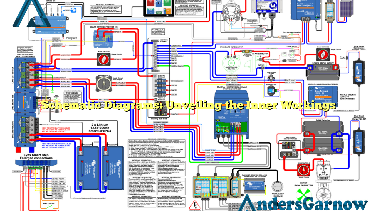
Schematic diagrams, also known as circuit diagrams, are graphical representations of electrical circuits and systems. They use standardized symbols to illustrate the connections between various components, such as resistors, capacitors, transistors, and voltage sources. These diagrams facilitate the understanding of complex systems and aid in troubleshooting and designing new circuits.
Advantages:
- Clear Visualization: Schematic diagrams provide a concise and organized representation of intricate electrical systems, making it easier for engineers and technicians to comprehend.
- Troubleshooting Aid: With their detailed depiction of circuit connections, schematic diagrams assist in locating and rectifying faults or malfunctions efficiently.
- Designing Assistance: Engineers can use schematic diagrams as a blueprint for creating new circuits, ensuring accuracy and adherence to specifications.
Limitations:
- Complexity: Schematic diagrams can become intricate and challenging to interpret in complex systems with numerous components.
- No Physical Layout: Schematic diagrams do not provide information about the physical layout of components, which may be crucial for some applications.
- Technical Expertise: Interpreting schematic diagrams requires a certain level of technical knowledge, limiting their accessibility to non-experts.
2. Components of a Schematic Diagram
A schematic diagram consists of various elements that collectively convey the circuit’s functioning. These key components include:
| Component | Description |
|---|---|
| Symbols | Standardized graphical representations of electrical components used to represent their function and characteristics. |
| Lines | Connect symbols, indicating electrical connections and pathways between components. |
| Labels | Provide additional information about specific components or nodes within the circuit. |
| Arrows | Indicate the flow of current or signal through the circuit. |
| Numbers | Represent component values, such as resistance or voltage. |
3. Alternatives to Schematic Diagrams
While schematic diagrams are widely used and highly effective, alternate methods exist for representing circuitry. Some alternatives include:
- Block Diagrams: Provide a high-level overview of the system, focusing on the interconnections between subsystems or functional blocks.
- Wiring Diagrams: Emphasize the physical layout and connections between components, commonly used in industries like automotive and aerospace.
- PCB Layouts: Detail the physical arrangement of components on a printed circuit board (PCB) and their interconnections.
4. Frequently Asked Questions (FAQ)
Q: Can schematic diagrams be used for both analog and digital circuits?
A: Yes, schematic diagrams are versatile and can represent both analog and digital circuits effectively.
Q: Are schematic diagrams only used in electrical engineering?
A: While schematic diagrams are primarily used in electrical engineering, they can also be beneficial in other fields, such as electronics, telecommunications, and even computer science.
Q: Can I create my own symbols on a schematic diagram?
A: While it is possible to create custom symbols, it is generally recommended to adhere to standardized symbols for clarity and ease of understanding.
In Conclusion
Schematic diagrams are an indispensable tool in the realm of electrical engineering. They provide a clear, standardized representation of circuits, aiding in troubleshooting, designing, and understanding complex systems. While they have their limitations, the benefits of schematic diagrams far outweigh the drawbacks, making them an essential aspect of modern engineering practices. So, embrace the power of schematic diagrams and unlock the secrets of electrical systems!
